Achieve pixel perfection with SZ420757N and STM32F302VC
Visualize, customize, amaze: 7x10 red dot magic!
Published Jul 22, 2025
Click board™
7x10 R Click
Dev. board
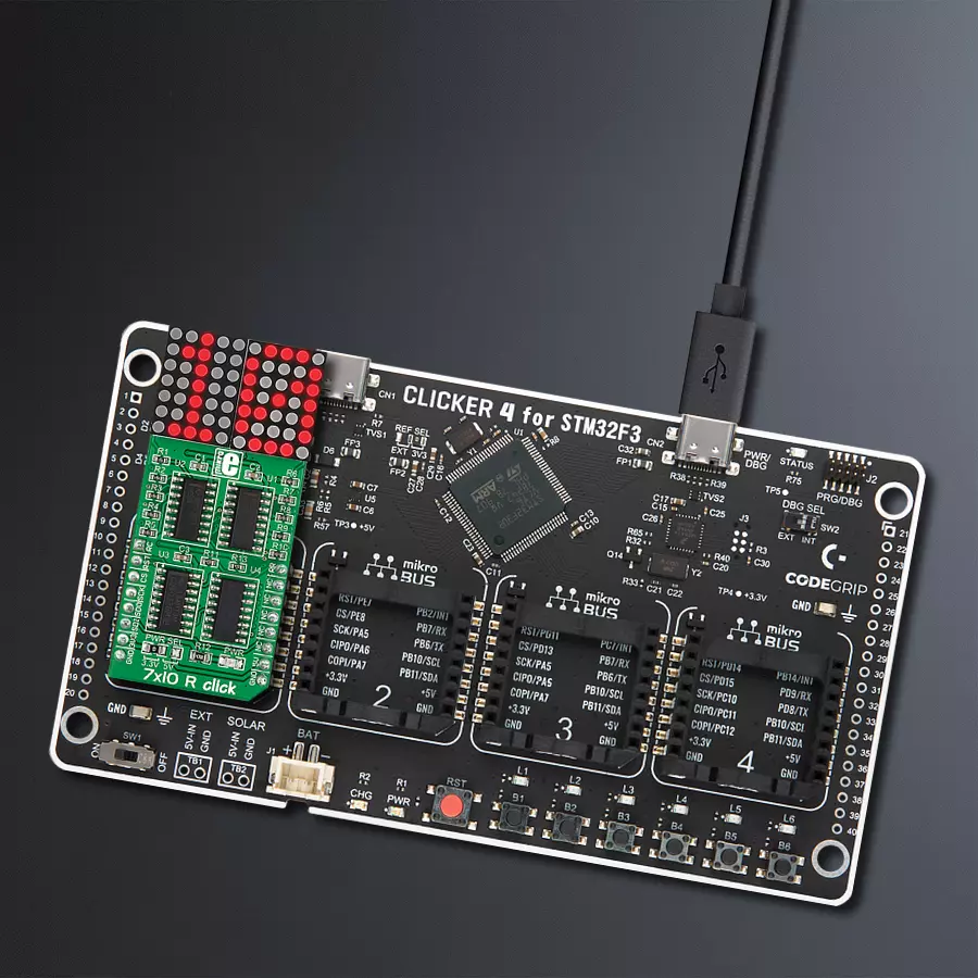
CLICKER 4 for STM32F302VCT6
Compiler
NECTO Studio
MCU
STM32F302VC
Our 7x10 red LED dot matrix display solution offers a versatile canvas for visual creativity, making it perfect for applications ranging from scrolling messages to pixel art and real-time data visualization
A
A
Hardware Overview
How does it work?
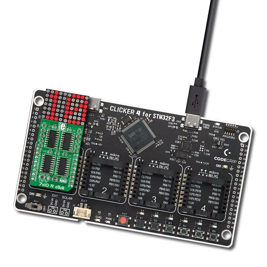
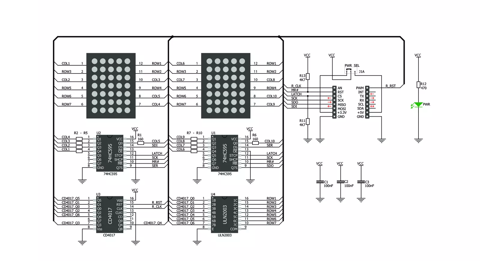
7x10 R Click is based on two SZ420757N, red LED dot matrix modules from Wuxi Ark. A single LED matrix module is composed of 35 LED elements grouped in rows and columns. The LED elements in one row have their cathodes connected and routed to a single-row pin. The LED elements in one column have their anodes connected and routed to a single-column pin. Multiplexed like this, modules have a fairly low number of pins (12 per module), making them suitable to be driven by shift registers and a decade of counter ICs. The driver circuit consists of two 74HC595 - 8bit, serial input - parallel output shift registers, one CD4017 - a Jonson topology decade counter with ten outputs, and one ULN2003A - an IC with seven integrated Darlington transistor pairs, all
chips produced by Texas Instruments. The shift registers are used to polarize the anodes on the columns of the LED displays. To complete the LED's current path, their cathodes must be connected to the ground. This is where the CD4017 and ULN2003 ICs are used. The ULN2003 IC drives rows of the dot matrix displays by sinking the current on the active row. To activate one of the seven input channels of the ULN2003 IC, the CD4017 decade counter IC is used. The design of the decade counter allows only one row to be active at a time. So, to see the complete picture on an LED matrix, the row scanning has to be fast enough so that the effect called persistent vision takes place. It produces an illusion of a complete image, even if only one row is seen at a time -
because the human eye cannot detect very fast changes in light. 7x10 R Click uses a 4-Wire SPI serial interface of the 74HC595 shift registers to communicate with the host MCU. The shift registers are chained together and can be reset over the RST pin. The clock and the reset inputs of the CD4017 are controlled by the RC and RR pins. This Click board™ can operate with either 3.3V or 5V logic voltage levels selected via the PWR SEL jumper. This way, both 3.3V and 5V capable MCUs can use the communication lines properly. Also, this Click board™ comes equipped with a library containing easy-to-use functions and an example code that can be used as a reference for further development.

Features overview
Development board
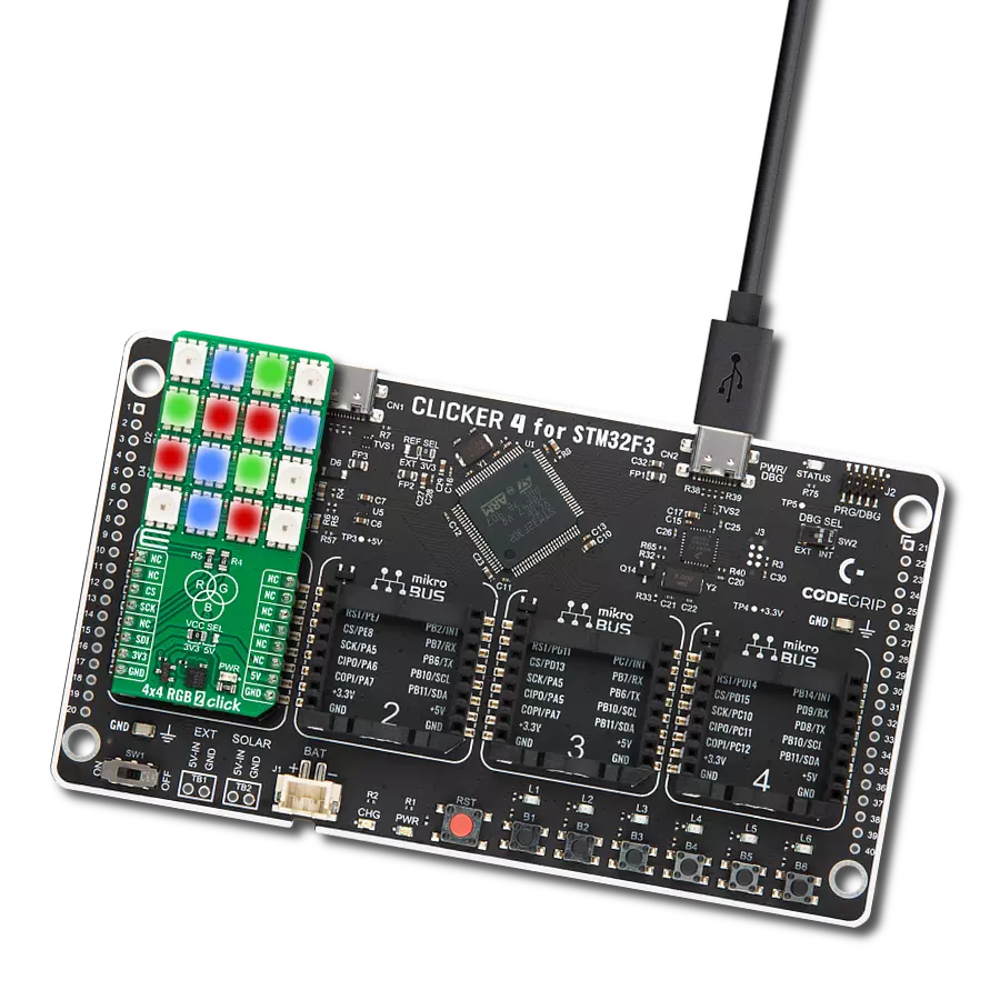
Clicker 4 for STM32F3 is a compact development board designed as a complete solution, you can use it to quickly build your own gadgets with unique functionalities. Featuring a STM32F302VCT6, four mikroBUS™ sockets for Click boards™ connectivity, power managment, and more, it represents a perfect solution for the rapid development of many different types of applications. At its core, there is a STM32F302VCT6 MCU, a powerful microcontroller by STMicroelectronics, based on the high-
performance Arm® Cortex®-M4 32-bit processor core operating at up to 168 MHz frequency. It provides sufficient processing power for the most demanding tasks, allowing Clicker 4 to adapt to any specific application requirements. Besides two 1x20 pin headers, four improved mikroBUS™ sockets represent the most distinctive connectivity feature, allowing access to a huge base of Click boards™, growing on a daily basis. Each section of Clicker 4 is clearly marked, offering an intuitive and clean interface. This makes working with the development
board much simpler and thus, faster. The usability of Clicker 4 doesn’t end with its ability to accelerate the prototyping and application development stages: it is designed as a complete solution which can be implemented directly into any project, with no additional hardware modifications required. Four mounting holes [4.2mm/0.165”] at all four corners allow simple installation by using mounting screws. For most applications, a nice stylish casing is all that is needed to turn the Clicker 4 development board into a fully functional, custom design.

Microcontroller Overview
MCU Card / MCU

Architecture
ARM Cortex-M4
MCU Memory (KB)
256
Silicon Vendor
STMicroelectronics
Pin count
100
RAM (Bytes)
40960
Used MCU Pins
mikroBUS™ mapper
Take a closer look
Click board™ Schematic
Step by step
Project assembly

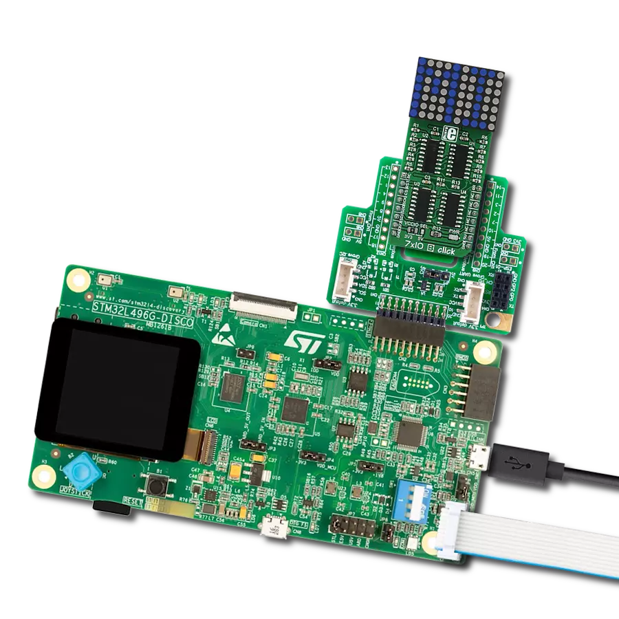
Start by selecting your development board and Click board™. Begin with the CLICKER 4 for STM32F302VCT6 as your development board.


Track your results in real time
Application Output
1. Application Output - In Debug mode, the 'Application Output' window enables real-time data monitoring, offering direct insight into execution results. Ensure proper data display by configuring the environment correctly using the provided tutorial.

2. UART Terminal - Use the UART Terminal to monitor data transmission via a USB to UART converter, allowing direct communication between the Click board™ and your development system. Configure the baud rate and other serial settings according to your project's requirements to ensure proper functionality. For step-by-step setup instructions, refer to the provided tutorial.

3. Plot Output - The Plot feature offers a powerful way to visualize real-time sensor data, enabling trend analysis, debugging, and comparison of multiple data points. To set it up correctly, follow the provided tutorial, which includes a step-by-step example of using the Plot feature to display Click board™ readings. To use the Plot feature in your code, use the function: plot(*insert_graph_name*, variable_name);. This is a general format, and it is up to the user to replace 'insert_graph_name' with the actual graph name and 'variable_name' with the parameter to be displayed.

Software Support
Library Description
This library contains API for 7x10 R Click driver.
Key functions:
c7x10r_draw_pixel- Drawing the pixel on the displayc7x10r_draw_char- Drawing the character on the displayc7x10r_draw_number- Drawing the number on the display
Open Source
Code example
The complete application code and a ready-to-use project are available through the NECTO Studio Package Manager for direct installation in the NECTO Studio. The application code can also be found on the MIKROE GitHub account.
/*!
 * @file main.c
 * @brief c7x10R Click example
 *
 * # Description
 * This demo example shows a drawing of pixels, characters and a number on the screen.
 *
 * The demo application is composed of two sections :
 *
 * ## Application Init
 * Configuring the Click board.
 *
 * ## Application Task
 * Draws characters, numbers, and pixels to the display.
 *
 * @author Jelena Milosavljevic
 *
 */

#include "board.h"
#include "c7x10r.h"

// ------------------------------------------------------------------ VARIABLES

static c7x10r_t c7x10r;

// ------------------------------------------------------ APPLICATION FUNCTIONS

void application_init ( void ) {

    c7x10r_cfg_t c7x10r_cfg;  /**< Click config object. */

    //  Click initialization.

    c7x10r_cfg_setup( &c7x10r_cfg );
    C7X10R_MAP_MIKROBUS( c7x10r_cfg, MIKROBUS_1 );
    c7x10r_init( &c7x10r, &c7x10r_cfg );
}

void application_task ( void ) {

    c7x10r_pixel_t pixel;
    uint8_t cnt;
    uint8_t cnt_x;
    uint8_t cnt_y;

    // CHAR PROCEDURE

    for ( cnt = 'A'; cnt < 'Z'; cnt+=2 ) {

        c7x10r_draw_char( &c7x10r, cnt, C7X10R_DISPLAY_LEFT, C7X10R_DISPLAY_DELAY_50MS );
        c7x10r_draw_char( &c7x10r, cnt + 1, C7X10R_DISPLAY_RIGHT | C7X10R_DISPLAY_REFRESH, C7X10R_DISPLAY_DELAY_50MS );

        Delay_ms ( 1000 );
    }

    // COUNTER PROCEDURE

    for ( cnt = 0; cnt < 15; cnt++ ) {

        c7x10r_draw_number( &c7x10r, cnt, C7X10R_DISPLAY_DELAY_50MS );

        Delay_ms ( 500 );
    }

    // PIXELS PROCEDURE

    for ( cnt_x = 0; cnt_x <= 7; cnt_x++ ) {

        for ( cnt_y = 0; cnt_y <= 10; cnt_y++ ) {

            pixel.cord_x = cnt_x;
            pixel.cord_y = cnt_y;
            c7x10r_draw_pixel( &c7x10r, &pixel, C7X10R_DISPLAY_PIXEL_STORAGE, C7X10R_DISPLAY_DELAY_20MS );

            pixel.cord_x = cnt_x;
            pixel.cord_y = cnt_y + 1;
            c7x10r_draw_pixel( &c7x10r, &pixel, C7X10R_DISPLAY_PIXEL_REFRESH, C7X10R_DISPLAY_DELAY_20MS );
        }
    }
}

int main ( void )
{
    /* Do not remove this line or clock might not be set correctly. */
    #ifdef PREINIT_SUPPORTED
    preinit();
    #endif

    application_init( );

    for ( ; ; )
    {
        application_task( );
    }

    return 0;
}

// ------------------------------------------------------------------------ END
Additional Support
Resources
Category:LED Matrix