Command the movements of two-phase bipolar stepper motors with TC78H670FTG and TM4C129ENCZAD
Driver for two-phase bipolar stepper motors employing PWM chopper technology for control

Published Mar 15, 2024
Click board™
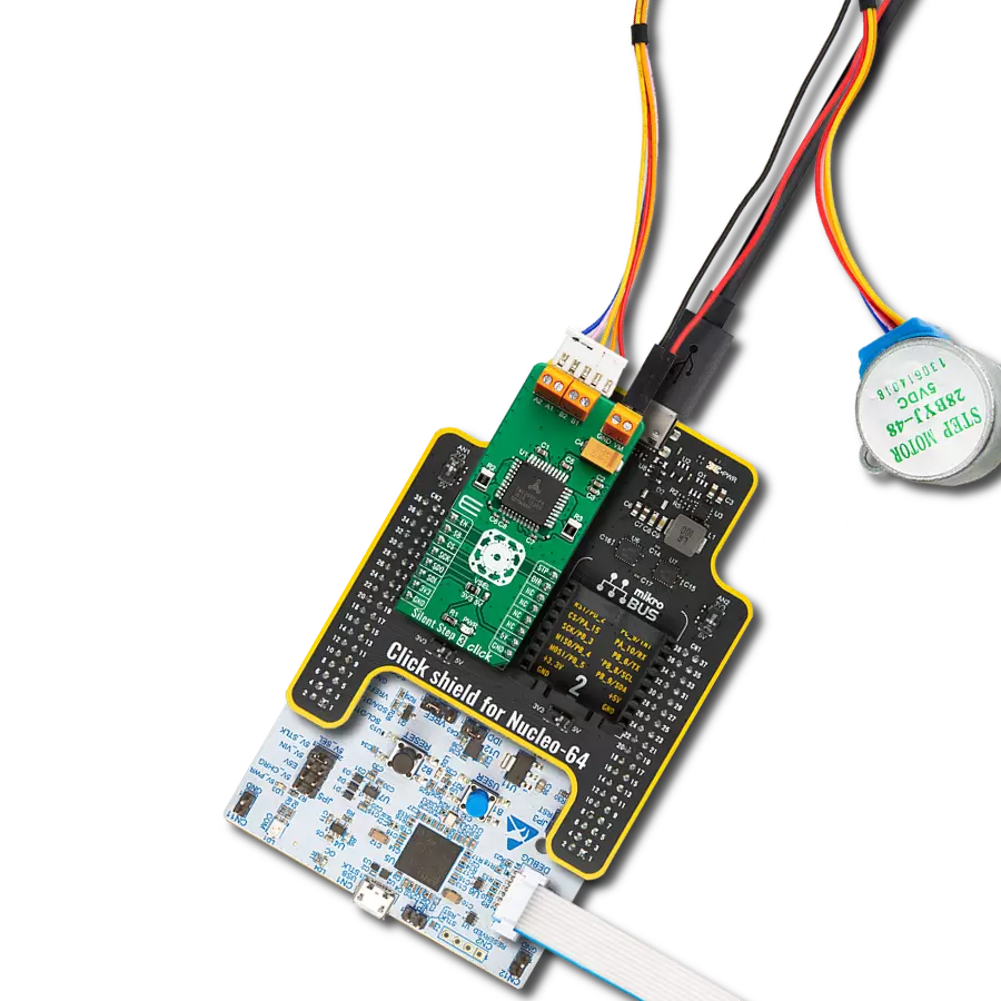
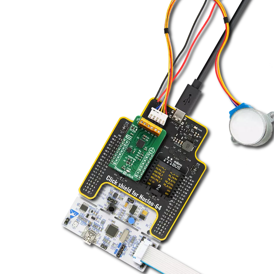
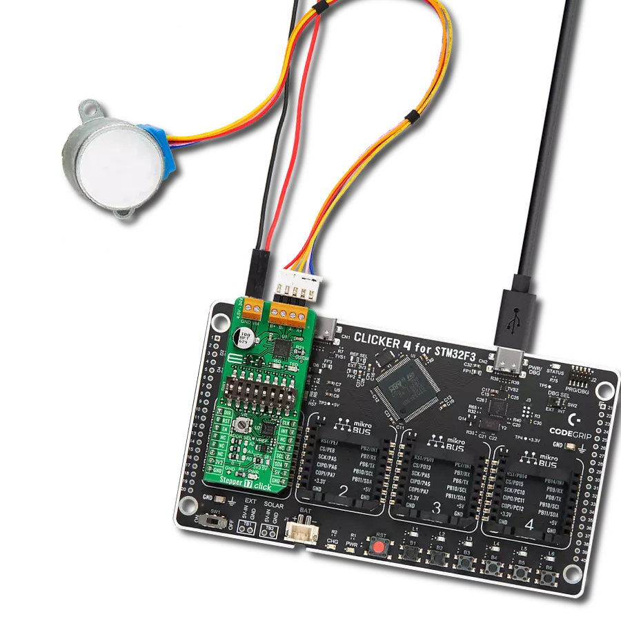
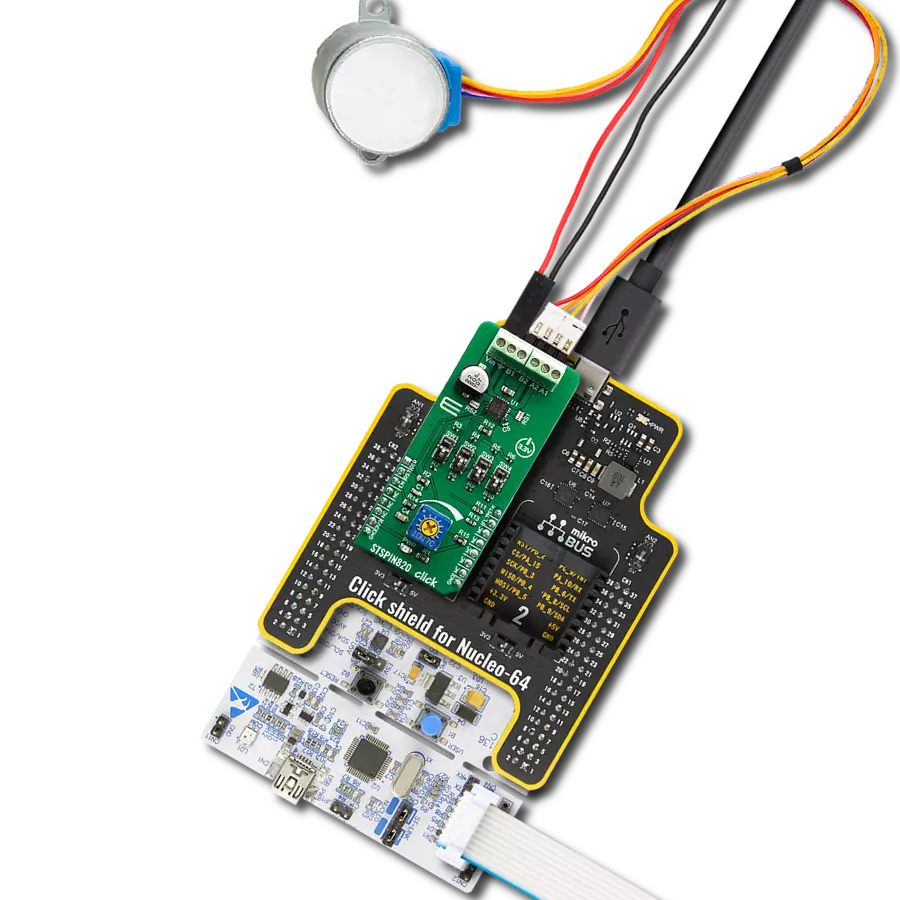
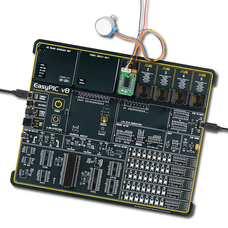
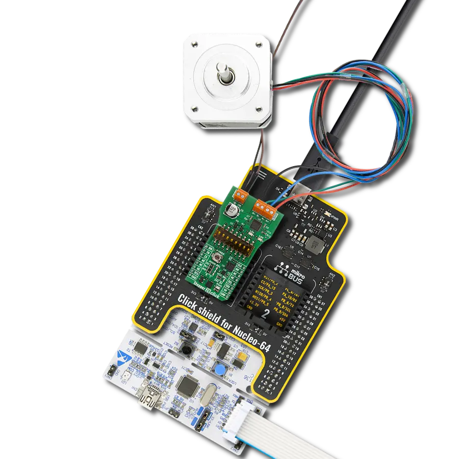
Stepper 8 Click
Dev. board
Fusion for Tiva v8
Compiler
NECTO Studio
MCU
TM4C129ENCZAD
An excellent choice for developers looking to enhance the functionality and performance of portable and compact devices requiring precise movement control
A
A
Hardware Overview
How does it work?
Stepper 8 Click is based on the TC78H670FTG, a clock-in and serial-controlled bipolar stepping motor driver from Toshiba. It can be used with a bipolar step motor; coils should be connected to the onboard screw terminals. There are two terminals used to connect each of the step motor coils. The third connector is used to connect an external voltage, ranging from 2.5V to 16V, depending on the used motor voltage requirements and current of 2A. Depending on ambient temperature and board conditions, the maximum output current may be further limited due to thermal considerations. It should be noted that without a valid external voltage connected to this terminal, the motor will not work. Stepper 8 Click can operate a bipolar stepper motor in full, half, quarter, 1/8, 1/16, 1/32, 1/64, 1/128 step operation. Thanks to internal safety features, such as thermal shutdown (TSD),
over current (ISD), motor load open (OPD), and under voltage lockout(UVLO), this Click board™ is perfectly suited for the rapid development of various stepper motor applications. This TC78H670FTG integrated driver offers a simple interface featuring a set of pins used to control the functions of the step motor. Since the number of pins exceeds the available mikroBUS™ general purpose pins, an additional port expander IC is used, exposing a 2-wire I2C interface for communication with the host MCU. The port expander IC is the PCA9538, an 8-bit port expander with the I2C interface. The MODE0-3 pins can be selected in Serial mode or CLK-IN mode. The control mode is set up by the input state of the MODE0-3 pins after releasing standby mode. Under the serial mode, it performs setting and motor control in the following 32-bit format using
SPI on mikroBUS™. For the motor control, each current value is set in the serial setting, and the output is updated to the set current value at the timing of the LATCH signal. To allow both Serial mode or CLK-IN mode on mikroBUS™, a TC7WH157 two-channel multiplexer from Toshiba is used. Selection is made using I2C communication with the PCA9538 port expander and changing the state of SELECT pins on multiplexers. This Click board™ can operate with either 3.3V or 5V logic voltage levels selected via the VCC SEL jumper. This way, both 3.3V and 5V capable MCUs can use the communication lines properly. Also, this Click board™ comes equipped with a library containing easy-to-use functions and an example code that can be used as a reference for further development.

Features overview
Development board
Fusion for TIVA v8 is a development board specially designed for the needs of rapid development of embedded applications. It supports a wide range of microcontrollers, such as different 32-bit ARM® Cortex®-M based MCUs from Texas Instruments, regardless of their number of pins, and a broad set of unique functions, such as the first-ever embedded debugger/programmer over a WiFi network. The development board is well organized and designed so that the end-user has all the necessary elements, such as switches, buttons, indicators, connectors, and others, in one place. Thanks to innovative manufacturing technology, Fusion for TIVA v8 provides a fluid and immersive working experience, allowing access
anywhere and under any circumstances at any time. Each part of the Fusion for TIVA v8 development board contains the components necessary for the most efficient operation of the same board. An advanced integrated CODEGRIP programmer/debugger module offers many valuable programming/debugging options, including support for JTAG, SWD, and SWO Trace (Single Wire Output)), and seamless integration with the Mikroe software environment. Besides, it also includes a clean and regulated power supply module for the development board. It can use a wide range of external power sources, including a battery, an external 12V power supply, and a power source via the USB Type-C (USB-C) connector.
Communication options such as USB-UART, USB HOST/DEVICE, CAN (on the MCU card, if supported), and Ethernet is also included. In addition, it also has the well-established mikroBUS™ standard, a standardized socket for the MCU card (SiBRAIN standard), and two display options for the TFT board line of products and character-based LCD. Fusion for TIVA v8 is an integral part of the Mikroe ecosystem for rapid development. Natively supported by Mikroe software tools, it covers many aspects of prototyping and development thanks to a considerable number of different Click boards™ (over a thousand boards), the number of which is growing every day.

Microcontroller Overview
MCU Card / MCU
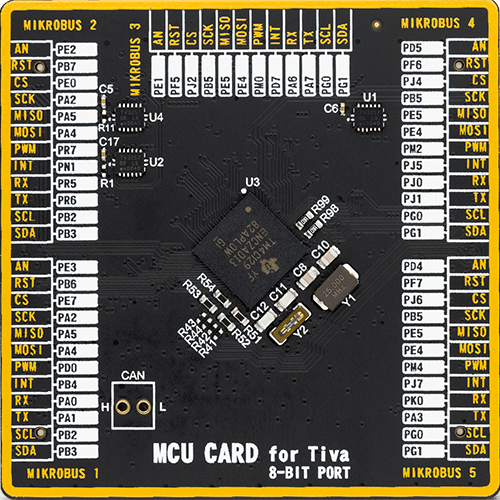
Type
8th Generation
Architecture
ARM Cortex-M4
MCU Memory (KB)
1024
Silicon Vendor
Texas Instruments
Pin count
212
RAM (Bytes)
262144
You complete me!
Accessories
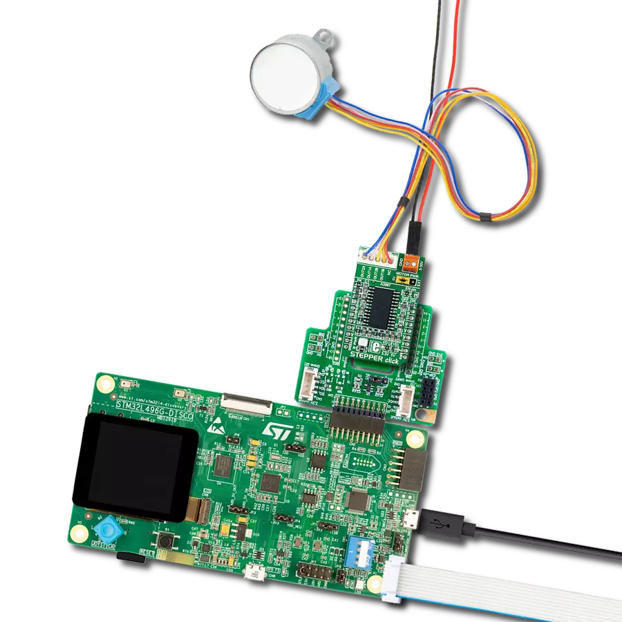
The 28BYJ-48 is an adaptable 5VDC stepper motor with a compact design, ideal for various applications. It features four phases, a speed variation ratio of 1/64, and a stride angle of 5.625°/64 steps, allowing precise control. The motor operates at a frequency of 100Hz and has a DC resistance of 50Ω ±7% at 25°C. It boasts an idle in-traction frequency greater than 600Hz and an idle out-traction frequency exceeding 1000Hz, ensuring reliability in different scenarios. With a self-positioning torque and in-traction torque both exceeding 34.3mN.m at 120Hz, the 28BYJ-48 offers robust performance. Its friction torque ranges from 600 to 1200 gf.cm, while the pull-in torque is 300 gf.cm. This motor makes a reliable and efficient choice for your stepper motor needs.

Used MCU Pins
mikroBUS™ mapper
Take a closer look
Click board™ Schematic

Step by step
Project assembly

Start by selecting your development board and Click board™. Begin with the Fusion for Tiva v8 as your development board.


Software Support
Library Description
This library contains API for Stepper 8 Click driver.
Key functions:
stepper8_set_direction- This function sets the motor direction by setting the DIR pin logic statestepper8_set_step_mode- This function sets the step mode resolution settingsstepper8_drive_motor- This function drives the motor for the specific number of steps at the selected speed
Open Source
Code example
The complete application code and a ready-to-use project are available through the NECTO Studio Package Manager for direct installation in the NECTO Studio. The application code can also be found on the MIKROE GitHub account.
/*!
 * @file main.c
 * @brief Stepper 8 Click example
 *
 * # Description
 * This example demonstrates the use of the Stepper 8 Click board by driving the
 * motor in both directions for a desired number of steps.
 *
 * The demo application is composed of two sections :
 *
 * ## Application Init
 * Initializes the driver and performs the Click default configuration.
 *
 * ## Application Task
 * Drives the motor clockwise for 200 full steps and then counter-clockiwse for 200 half
 * steps and 400 quarter steps with 2 seconds delay on driving mode change. All data is
 * being logged on the USB UART where you can track the program flow.
 *
 * @author Stefan Filipovic
 *
 */

#include "board.h"
#include "log.h"
#include "stepper8.h"

static stepper8_t stepper8;
static log_t logger;

void application_init ( void )
{
    log_cfg_t log_cfg;  /**< Logger config object. */
    stepper8_cfg_t stepper8_cfg;  /**< Click config object. */

    /**
     * Logger initialization.
     * Default baud rate: 115200
     * Default log level: LOG_LEVEL_DEBUG
     * @note If USB_UART_RX and USB_UART_TX
     * are defined as HAL_PIN_NC, you will
     * need to define them manually for log to work.
     * See @b LOG_MAP_USB_UART macro definition for detailed explanation.
     */
    LOG_MAP_USB_UART( log_cfg );
    log_init( &logger, &log_cfg );
    log_info( &logger, " Application Init " );

    // Click initialization.
    stepper8_cfg_setup( &stepper8_cfg );
    STEPPER8_MAP_MIKROBUS( stepper8_cfg, MIKROBUS_1 );
    err_t init_flag = stepper8_init( &stepper8, &stepper8_cfg );
    if ( ( I2C_MASTER_ERROR == init_flag ) || ( SPI_MASTER_ERROR == init_flag ) )
    {
        log_error( &logger, " Communication init." );
        for ( ; ; );
    }

    if ( STEPPER8_ERROR == stepper8_default_cfg ( &stepper8 ) )
    {
        log_error( &logger, " Default configuration." );
        for ( ; ; );
    }

    log_info( &logger, " Application Task " );
}

void application_task ( void )
{
    log_printf ( &logger, " Move 200 full steps clockwise, speed: slow\r\n\n" );
    stepper8_set_direction ( &stepper8, STEPPER8_DIR_CW );
    stepper8_set_step_mode ( &stepper8, STEPPER8_MODE_FULL_STEP );
    stepper8_drive_motor ( &stepper8, 200, STEPPER8_SPEED_SLOW );
    Delay_ms ( 1000 );
    Delay_ms ( 1000 );

    log_printf ( &logger, " Move 200 half steps counter-clockwise, speed: medium\r\n\n" );
    stepper8_set_direction ( &stepper8, STEPPER8_DIR_CCW );
    stepper8_set_step_mode ( &stepper8, STEPPER8_MODE_HALF_STEP );
    stepper8_drive_motor ( &stepper8, 200, STEPPER8_SPEED_MEDIUM );
    Delay_ms ( 1000 );
    Delay_ms ( 1000 );

    log_printf ( &logger, " Move 400 quarter steps counter-clockwise, speed: fast\r\n\n" );
    stepper8_set_direction ( &stepper8, STEPPER8_DIR_CCW );
    stepper8_set_step_mode ( &stepper8, STEPPER8_MODE_QUARTER_STEP );
    stepper8_drive_motor ( &stepper8, 400, STEPPER8_SPEED_FAST );
    Delay_ms ( 1000 );
    Delay_ms ( 1000 );
}

int main ( void )
{
    /* Do not remove this line or clock might not be set correctly. */
    #ifdef PREINIT_SUPPORTED
    preinit();
    #endif

    application_init( );

    for ( ; ; )
    {
        application_task( );
    }

    return 0;
}

// ------------------------------------------------------------------------ END
Additional Support
Resources
Category:Stepper