Achieve accurate and reliable AC/DC current sensing with TLI4970-D050T4 and STM32L496AG
Coreless magnetic current sensor for currents up to ±25A
Published Jul 22, 2025
Click board™
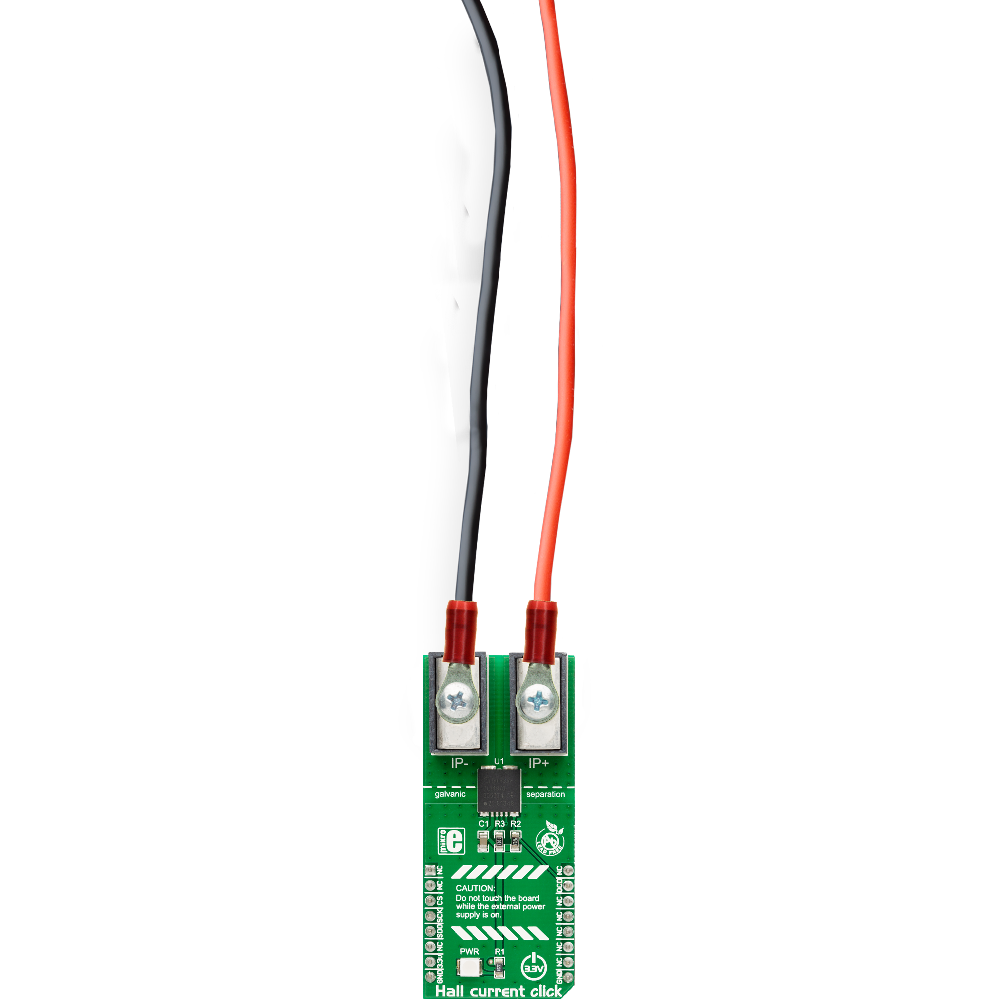
Hall Current Click
Dev. board
Discovery kit with STM32L496AG MCU
Compiler
NECTO Studio
MCU
STM32L496AG
AC/DC current sensor utilizing Hall technology, capable of measuring up to ±25A and certified according to industrial standards, ideal for use in both industrial and consumer applications
A
A
Hardware Overview
How does it work?
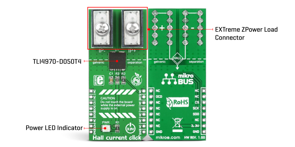
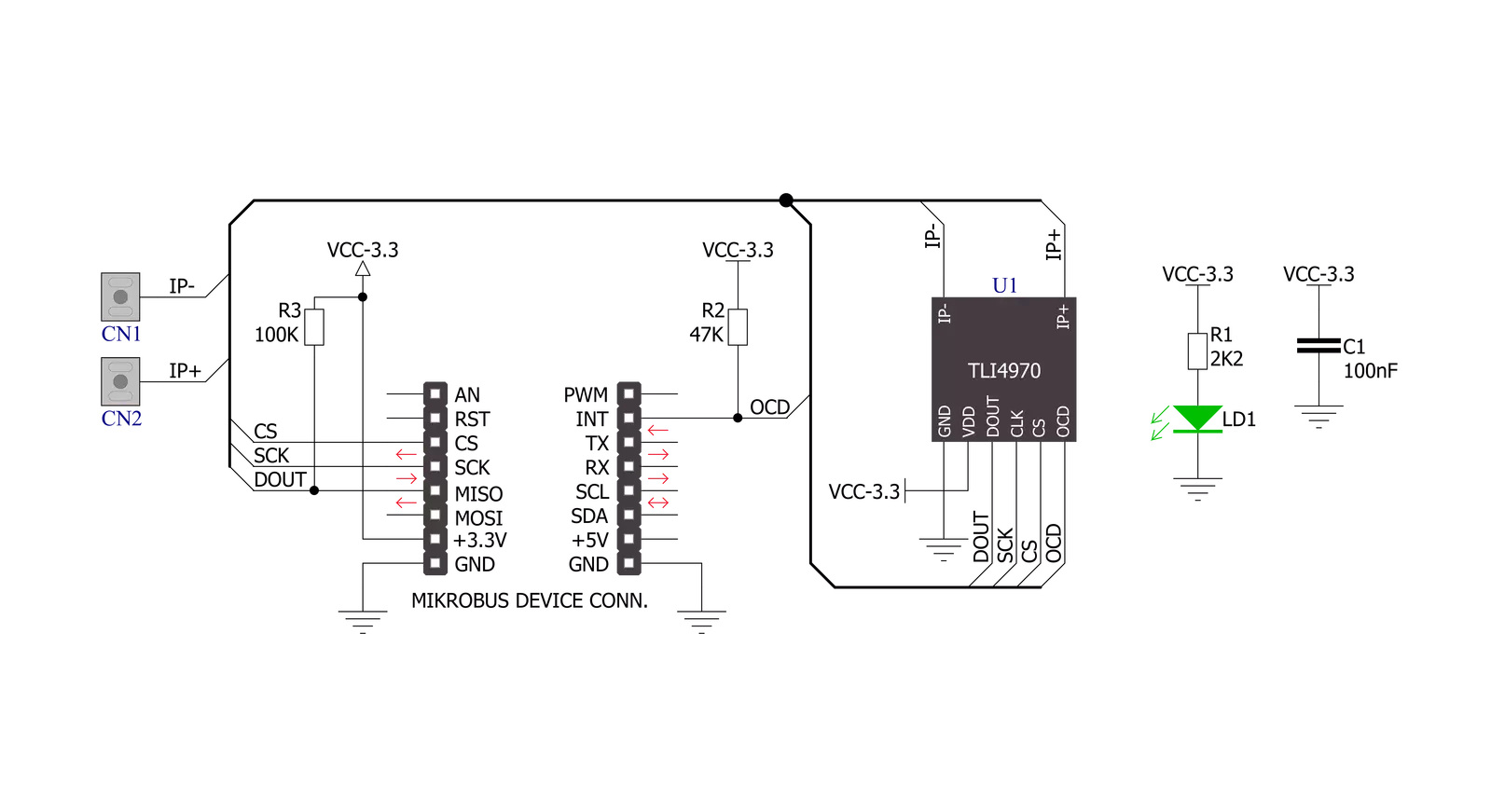
Hall Current Click is based on the TLI4970-D050T4, a high-precision digital current sensor designed for the current range of ±25A from Infineon Technology. The measurement principle allows galvanic isolation (functional isolation) between the primary conductor and the secondary interface. Based on a digital concept, the signal processing unit of the TLI4970-D050T4 already has integrated compensation and calibration, which means no further external measurements for compensation are needed. It represents a plug-and-play solution, easy to use in industrial and consumer applications. The differential measurement principle of the TLI4970-D050T4 achieves best-in-class suppression of stray magnetic fields with a highly linear output signal
without hysteresis. The accuracy of the TLI4970-D050T4 is comparable to closed-loop current measurement systems and even better than open-loop systems with magnetic cores. But in comparison to the open- and closed-loop systems, the TLI4970-D050T4 enables significantly less power consumption. Besides outstanding long-term stability of the output signal and a proprietary dynamic offset cancellation technique that guarantees low zero point error, the TLI4970-D050T4 offers superior performance. As mentioned, this Click board™ communicates with MCU through a standard unidirectional 16-bit SPI protocol to control and configure the TLI4970-D050T4 with a maximum SPI frequency of 5MHz. In addition to communication pins, this board also
possesses an additional pin marked as OCD, routed to the INT pin on the mikroBUS™ socket for over-current detection. For fast over-current detection, the raw analog signal from the Hall probes is fed into a programmable comparator with a programmable glitch filter to suppress the signal’s fast switching transients and avoid false triggers. This Click board™ can only be operated with a 3.3V logic voltage level. The board must perform appropriate logic voltage level conversion before using MCUs with different logic levels. However, the Click board™ comes equipped with a library containing functions and an example code that can be used as a reference for further development.
Features overview
Development board
The 32L496GDISCOVERY Discovery kit serves as a comprehensive demonstration and development platform for the STM32L496AG microcontroller, featuring an Arm® Cortex®-M4 core. Designed for applications that demand a balance of high performance, advanced graphics, and ultra-low power consumption, this kit enables seamless prototyping for a wide range of embedded solutions. With its innovative energy-efficient
architecture, the STM32L496AG integrates extended RAM and the Chrom-ART Accelerator, enhancing graphics performance while maintaining low power consumption. This makes the kit particularly well-suited for applications involving audio processing, graphical user interfaces, and real-time data acquisition, where energy efficiency is a key requirement. For ease of development, the board includes an onboard ST-LINK/V2-1
debugger/programmer, providing a seamless out-of-the-box experience for loading, debugging, and testing applications without requiring additional hardware. The combination of low power features, enhanced memory capabilities, and built-in debugging tools makes the 32L496GDISCOVERY kit an ideal choice for prototyping advanced embedded systems with state-of-the-art energy efficiency.

Microcontroller Overview
MCU Card / MCU

Architecture
ARM Cortex-M4
MCU Memory (KB)
1024
Silicon Vendor
STMicroelectronics
Pin count
169
RAM (Bytes)
327680
Used MCU Pins
mikroBUS™ mapper
Take a closer look
Click board™ Schematic
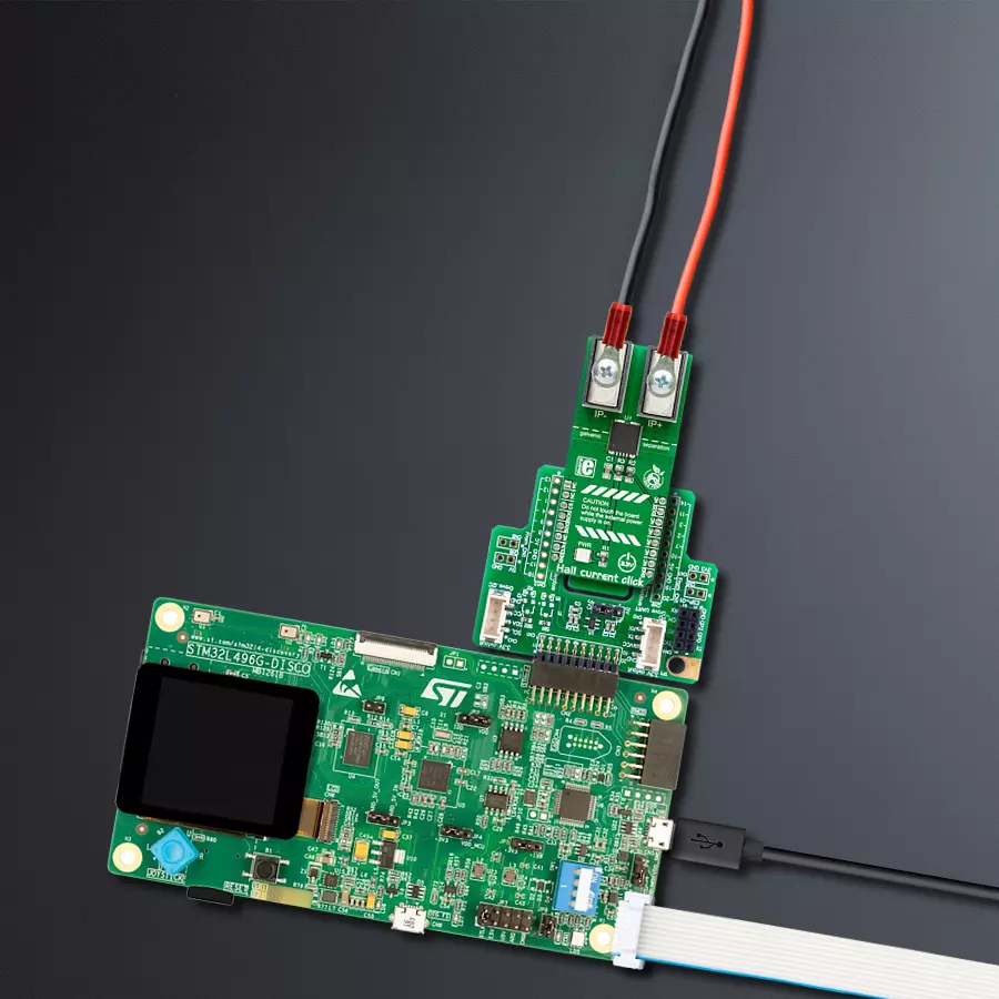
Step by step
Project assembly

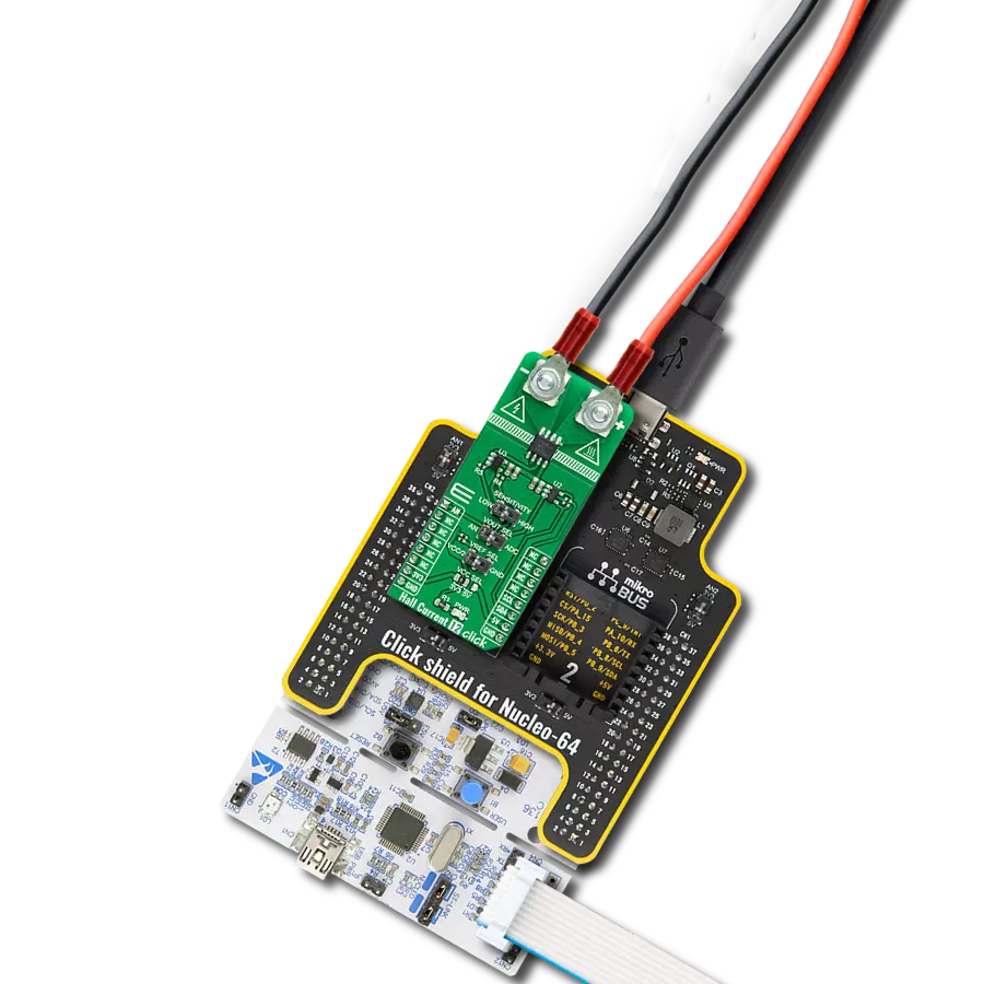
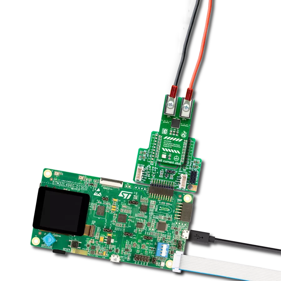
Start by selecting your development board and Click board™. Begin with the Discovery kit with STM32L496AG MCU as your development board.


Track your results in real time
Application Output
1. Application Output - In Debug mode, the 'Application Output' window enables real-time data monitoring, offering direct insight into execution results. Ensure proper data display by configuring the environment correctly using the provided tutorial.

2. UART Terminal - Use the UART Terminal to monitor data transmission via a USB to UART converter, allowing direct communication between the Click board™ and your development system. Configure the baud rate and other serial settings according to your project's requirements to ensure proper functionality. For step-by-step setup instructions, refer to the provided tutorial.

3. Plot Output - The Plot feature offers a powerful way to visualize real-time sensor data, enabling trend analysis, debugging, and comparison of multiple data points. To set it up correctly, follow the provided tutorial, which includes a step-by-step example of using the Plot feature to display Click board™ readings. To use the Plot feature in your code, use the function: plot(*insert_graph_name*, variable_name);. This is a general format, and it is up to the user to replace 'insert_graph_name' with the actual graph name and 'variable_name' with the parameter to be displayed.

Software Support
Library Description
This library contains API for Hall Current Click driver.
Key functions:
hallcurrent_read_data- Generic read 16-bit data functionhallcurrent_check_status- Check status of read data functionhallcurrent_read_current- Read electric current function
Open Source
Code example
The complete application code and a ready-to-use project are available through the NECTO Studio Package Manager for direct installation in the NECTO Studio. The application code can also be found on the MIKROE GitHub account.
/*!
 * \file
 * \brief HallCurrent Click example
 *
 * # Description
 * The application is current sensor.
 *
 * The demo application is composed of two sections :
 *
 * ## Application Init
 * Initialization driver enable's - SPI and start write log.
 *
 * ## Application Task
 * This is an example which demonstrates the use of Hall Current Click board.
 *
 * \author MikroE Team
 *
 */
// ------------------------------------------------------------------- INCLUDES

#include "board.h"
#include "log.h"
#include "hallcurrent.h"

// ------------------------------------------------------------------ VARIABLES

static hallcurrent_t hallcurrent;
static log_t logger;

// ------------------------------------------------------ APPLICATION FUNCTIONS

void application_init ( void )
{
    log_cfg_t log_cfg;
    hallcurrent_cfg_t cfg;

    /**
     * Logger initialization.
     * Default baud rate: 115200
     * Default log level: LOG_LEVEL_DEBUG
     * @note If USB_UART_RX and USB_UART_TX
     * are defined as HAL_PIN_NC, you will
     * need to define them manually for log to work.
     * See @b LOG_MAP_USB_UART macro definition for detailed explanation.
     */
    LOG_MAP_USB_UART( log_cfg );
    log_init( &logger, &log_cfg );
    log_info( &logger, "---- Application Init ----" );

    //  Click initialization.
    hallcurrent_cfg_setup( &cfg );
    HALLCURRENT_MAP_MIKROBUS( cfg, MIKROBUS_1 );
    hallcurrent_init( &hallcurrent, &cfg );

    HALLCURRENT_SET_DATA_SAMPLE_EDGE;

    log_printf( &logger,"------------------------\r\n" );
    log_printf( &logger,  "       Hall Current     \r\n" );
    log_printf( &logger, "------------------------\r\n" );
}

void application_task ( void )
{
    log_printf( &logger, " Current : %.3f A \r\n", hallcurrent_read_current( &hallcurrent ) );
    log_printf( &logger, "------------------------\r\n" );
    Delay_ms ( 1000 );
}

int main ( void )
{
    /* Do not remove this line or clock might not be set correctly. */
    #ifdef PREINIT_SUPPORTED
    preinit();
    #endif

    application_init( );

    for ( ; ; )
    {
        application_task( );
    }

    return 0;
}


// ------------------------------------------------------------------------ END
Additional Support
Resources
Category:Current sensor