Experience the ideal temperature in your surroundings with TMP126 and STM32F207ZG
Transform your temperature monitoring approach!

Published Nov 11, 2023
Click board™
Thermo 29 Click
Dev. board
UNI-DS v8
Compiler
NECTO Studio
MCU
STM32F207ZG
We prioritize your well-being by delivering reliable temperature data to help you create a healthier and more cost-effective environment.
A
A
Hardware Overview
How does it work?
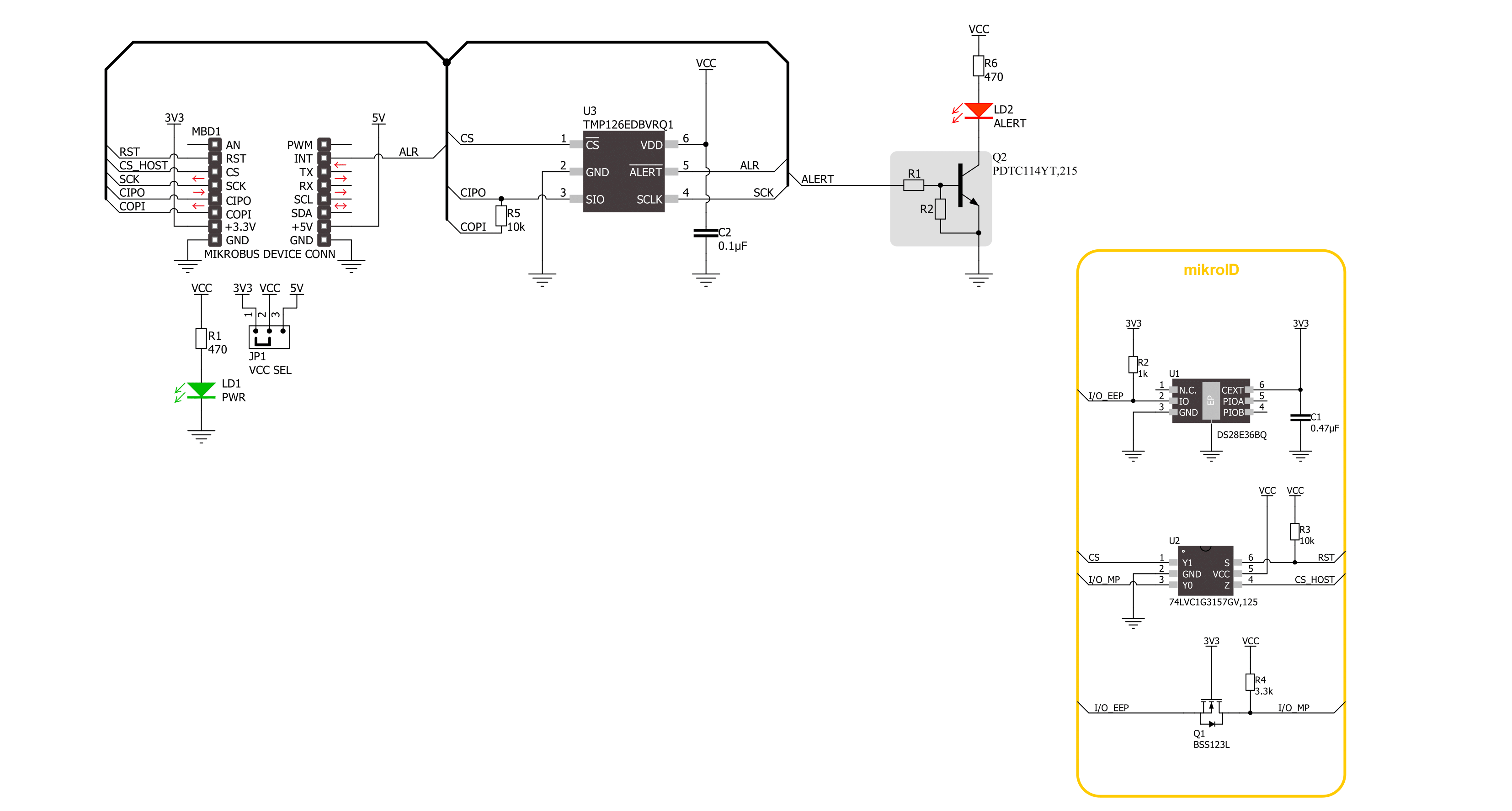
Thermo 29 Click is based on the TMP126, a digital output temperature sensor from Texas Instruments with increased reliability and improved accuracy specifications optimal for thermal management and protection applications. The TMP126 consists of an internal thermal BJT (factory calibrated on a NIST traceable setup), a high-resolution analog-to-digital converter (ADC), a data processing circuit, and serial interface logic functions in one package. The voltage is digitized and converted to a 14-bit temperature result in degrees Celsius, giving a fully calibrated digital output with outstanding accuracy of up to ±0.25°C and temperature resolution of 0.03125°C per LSB, typical over a temperature range of 20°C to 30°C. This Click
board™ communicates with MCU using a 3-wire SPI-compatible interface with a maximum frequency of 10MHz for data transfer and configuration of the TMP126. Using the Mode bit in the configuration register, the TMP126 can operate in various conversion modes, including continuous, one-shot, and shutdown modes. These modes provide flexibility to use the board in the most power-efficient way necessary for the intended application. The TMP126 also includes advanced features for increased reliability in harsh environments. These include an optional CRC checksum for data integrity, programmable alert limits, a temperature slew rate warning, and an enhanced operating temperature range. An alarm (interrupt) signal, marked as ALR and routed to
the interrupt pin of the mikroBUS™ socket, is alarming when a specific temperature event occurs that depends on the value of the temperature reading relative to programmable limits. In addition to the ALR pin, this function can be visually identified by a red LED marked as ALERT. This Click board™ can operate with either 3.3V or 5V logic voltage levels selected via the VCC SEL jumper. This way, both 3.3V and 5V capable MCUs can use the communication lines properly. Also, this Click board™ comes equipped with a library containing easy-to-use functions and an example code that can be used as a reference for further development.

Features overview
Development board
UNI-DS v8 is a development board specially designed for the needs of rapid development of embedded applications. It supports a wide range of microcontrollers, such as different STM32, Kinetis, TIVA, CEC, MSP, PIC, dsPIC, PIC32, and AVR MCUs regardless of their number of pins, and a broad set of unique functions, such as the first-ever embedded debugger/programmer over WiFi. The development board is well organized and designed so that the end-user has all the necessary elements, such as switches, buttons, indicators, connectors, and others, in one place. Thanks to innovative manufacturing technology, UNI-DS v8 provides a fluid and immersive working experience, allowing access anywhere and under any
circumstances at any time. Each part of the UNI-DS v8 development board contains the components necessary for the most efficient operation of the same board. An advanced integrated CODEGRIP programmer/debugger module offers many valuable programming/debugging options, including support for JTAG, SWD, and SWO Trace (Single Wire Output)), and seamless integration with the Mikroe software environment. Besides, it also includes a clean and regulated power supply module for the development board. It can use a wide range of external power sources, including a battery, an external 12V power supply, and a power source via the USB Type-C (USB-C) connector. Communication options such as USB-UART, USB
HOST/DEVICE, CAN (on the MCU card, if supported), and Ethernet is also included. In addition, it also has the well-established mikroBUS™ standard, a standardized socket for the MCU card (SiBRAIN standard), and two display options for the TFT board line of products and character-based LCD. UNI-DS v8 is an integral part of the Mikroe ecosystem for rapid development. Natively supported by Mikroe software tools, it covers many aspects of prototyping and development thanks to a considerable number of different Click boards™ (over a thousand boards), the number of which is growing every day.

Microcontroller Overview
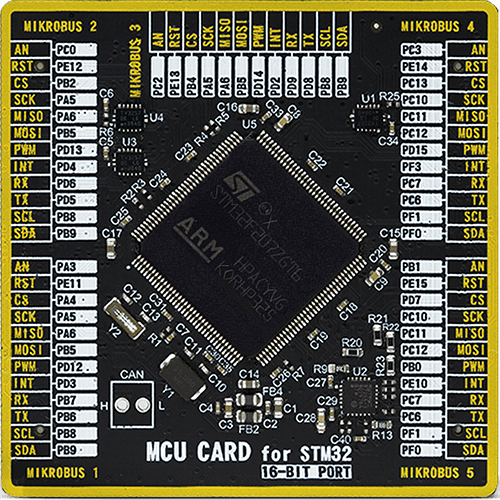
MCU Card / MCU
Type
8th Generation
Architecture
ARM Cortex-M3
MCU Memory (KB)
1024
Silicon Vendor
STMicroelectronics
Pin count
144
RAM (Bytes)
131072
Used MCU Pins
mikroBUS™ mapper
Take a closer look
Click board™ Schematic
Step by step
Project assembly

Start by selecting your development board and Click board™. Begin with the UNI-DS v8 as your development board.


Software Support
Library Description
This library contains API for Thermo 29 Click driver.
Key functions:
thermo29_read_unique_id- This function reads the device unique ID words (6 bytes in total).thermo29_get_alert_pin- This function returns the alert pin logic state.thermo29_read_temperature- This function reads the temperature measurement in degrees Celsius.
Open Source
Code example
The complete application code and a ready-to-use project are available through the NECTO Studio Package Manager for direct installation in the NECTO Studio. The application code can also be found on the MIKROE GitHub account.
/*!
 * @file main.c
 * @brief Thermo 29 Click example
 *
 * # Description
 * This example demonstrates the use of Thermo 29 Click board by reading and displaying
 * the temperature measurements.
 *
 * The demo application is composed of two sections :
 *
 * ## Application Init
 * Initializes the driver and logger, and performs the Click default configuration which enables
 * continuous conversion and sets the conversion rate to 1 Hz with a data ready flag enabled on
 * the alert pin. After that, reads and displays the device 48-bit unique ID.
 *
 * ## Application Task
 * Waits for the data ready alert flag, then reads the temperature measurement in Celsius
 * and displays the results on the USB UART approximately once per second.
 *
 * @author Stefan Filipovic
 *
 */

#include "board.h"
#include "log.h"
#include "thermo29.h"

static thermo29_t thermo29;
static log_t logger;

void application_init ( void )
{
    log_cfg_t log_cfg;  /**< Logger config object. */
    thermo29_cfg_t thermo29_cfg;  /**< Click config object. */

    /**
     * Logger initialization.
     * Default baud rate: 115200
     * Default log level: LOG_LEVEL_DEBUG
     * @note If USB_UART_RX and USB_UART_TX
     * are defined as HAL_PIN_NC, you will
     * need to define them manually for log to work.
     * See @b LOG_MAP_USB_UART macro definition for detailed explanation.
     */
    LOG_MAP_USB_UART( log_cfg );
    log_init( &logger, &log_cfg );
    log_info( &logger, " Application Init " );

    // Click initialization.
    thermo29_cfg_setup( &thermo29_cfg );
    THERMO29_MAP_MIKROBUS( thermo29_cfg, MIKROBUS_1 );
    if ( SPI_MASTER_ERROR == thermo29_init( &thermo29, &thermo29_cfg ) )
    {
        log_error( &logger, " Communication init." );
        for ( ; ; );
    }

    if ( THERMO29_ERROR == thermo29_default_cfg ( &thermo29 ) )
    {
        log_error( &logger, " Default configuration." );
        for ( ; ; );
    }

    uint16_t unique_id[ 3 ];
    if ( THERMO29_OK == thermo29_read_unique_id ( &thermo29, unique_id ) )
    {
        log_printf ( &logger, " Device Unique ID: 0x%.2X%.2X%.2X\r\n",
                     unique_id[ 0 ], unique_id[ 1 ], unique_id[ 2 ] );
    }

    log_info( &logger, " Application Task " );
}

void application_task ( void )
{
    float temperature;
    // Wait for the data ready alert flag
    while ( thermo29_get_alert_pin ( &thermo29 ) );

    if ( ( THERMO29_OK == thermo29_clear_alert_status ( &thermo29 ) ) &&
         ( THERMO29_OK == thermo29_read_temperature ( &thermo29, &temperature ) ) )
    {
        log_printf ( &logger, " Temperature: %.2f degC\r\n\n", temperature );
    }
}

int main ( void )
{
    /* Do not remove this line or clock might not be set correctly. */
    #ifdef PREINIT_SUPPORTED
    preinit();
    #endif

    application_init( );

    for ( ; ; )
    {
        application_task( );
    }

    return 0;
}

// ------------------------------------------------------------------------ END


