Protect circuits from overcurrent and overvoltage with eFuse and STM32F100ZE
Limiting faults, maximizing safety: Redefine protection with us

Published Oct 12, 2023
Click board™
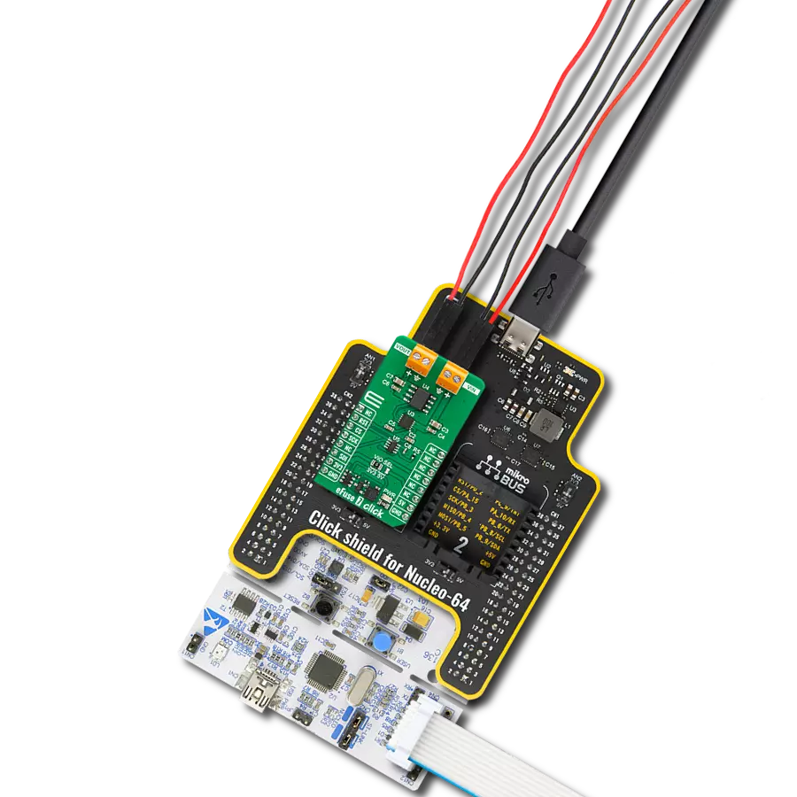
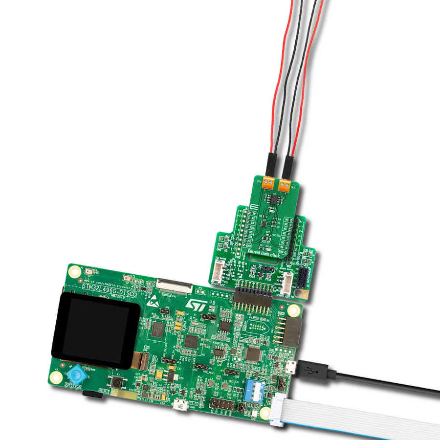
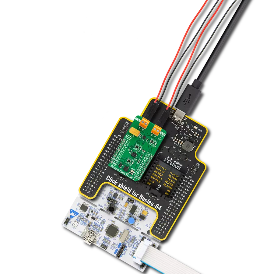
eFuse 5 Click
Dev. board
Fusion for STM32 v8
Compiler
NECTO Studio
MCU
STM32F100ZE
Experience the future of electronic circuit protection with our eFuse device, where precision control ensures your systems remain secure and perform optimally, even in challenging conditions
A
A
Hardware Overview
How does it work?
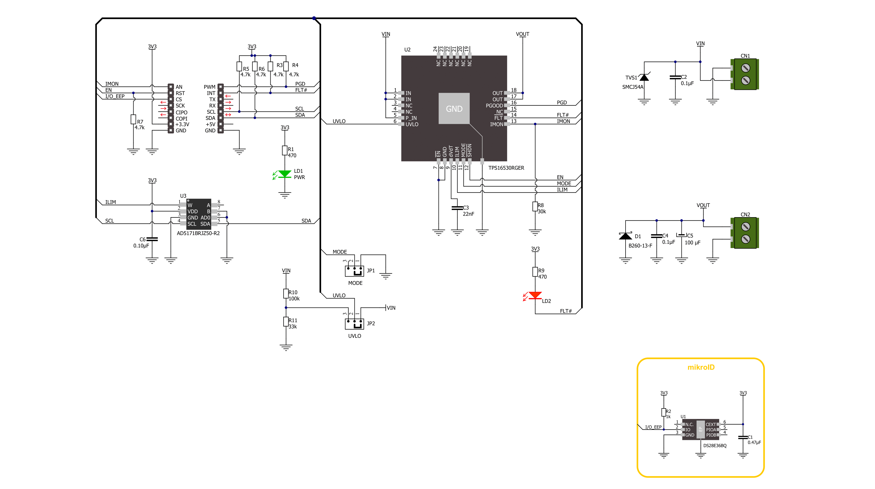
eFuse 5 Click is based on the TPS16530, an industrial eFuse from Texas Instruments. The TPS25940 provides robust protection for all systems and applications powered by an external power supply from 4.5V to 58V. Load, source, and device protections are provided with many programmable features, including undervoltage lockout selectable via UVLO SEL jumper and the fast response short circuit protection that immediately isolates the faulty load from the input supply when a short circuit is detected. The TPS16530 also allows users to program the overcurrent limit threshold between 0.6A and 4.5A via an external I2C-configurable digital
potentiometer, the AD5171 from Analog Devices. The TPS16530 can be put in low-power Shutdown mode using the EN pin of the mikroBUS™ socket, offering a switch operation to turn ON/OFF the eFuse. It also allows flexibility to configure the device between the two current-limiting fault responses (latch off and auto-retry). Selection is made by positioning SMD jumpers marked MODE SEL to the appropriate position marked GND or NC (GND is for automatic restart mode response during current limit and thermal fault, while NC is for latch off). For system status monitoring and downstream load control, the TPS16530 provides one fault signal, which can be visually detected
via the red FLT LED or the FLT pin on the mikroBUS™ socket, and a precise current monitor output available on the MON pin of the mikroBUS™ socket. Besides, the TPS16530 also features an open drain Power good (PGDD) indicator output, which can control downstream loads like DC/DC converters. This Click board™ can be operated only with a 3.3V logic voltage level. The board must perform appropriate logic voltage level conversion before using MCUs with different logic levels. Also, it comes equipped with a library containing functions and an example code that can be used as a reference for further development.

Features overview
Development board
Fusion for STM32 v8 is a development board specially designed for the needs of rapid development of embedded applications. It supports a wide range of microcontrollers, such as different 32-bit ARM® Cortex®-M based MCUs from STMicroelectronics, regardless of their number of pins, and a broad set of unique functions, such as the first-ever embedded debugger/programmer over WiFi. The development board is well organized and designed so that the end-user has all the necessary elements, such as switches, buttons, indicators, connectors, and others, in one place. Thanks to innovative manufacturing technology, Fusion for STM32 v8 provides a fluid and immersive working experience, allowing
access anywhere and under any circumstances at any time. Each part of the Fusion for STM32 v8 development board contains the components necessary for the most efficient operation of the same board. An advanced integrated CODEGRIP programmer/debugger module offers many valuable programming/debugging options, including support for JTAG, SWD, and SWO Trace (Single Wire Output)), and seamless integration with the Mikroe software environment. Besides, it also includes a clean and regulated power supply module for the development board. It can use a wide range of external power sources, including a battery, an external 12V power supply, and a power source via the USB Type-C (USB-C) connector.
Communication options such as USB-UART, USB HOST/DEVICE, CAN (on the MCU card, if supported), and Ethernet is also included. In addition, it also has the well-established mikroBUS™ standard, a standardized socket for the MCU card (SiBRAIN standard), and two display options for the TFT board line of products and character-based LCD. Fusion for STM32 v8 is an integral part of the Mikroe ecosystem for rapid development. Natively supported by Mikroe software tools, it covers many aspects of prototyping and development thanks to a considerable number of different Click boards™ (over a thousand boards), the number of which is growing every day.

Microcontroller Overview
MCU Card / MCU
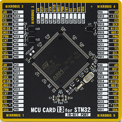
Type
8th Generation
Architecture
ARM Cortex-M3
MCU Memory (KB)
512
Silicon Vendor
STMicroelectronics
Pin count
144
RAM (Bytes)
32768
Used MCU Pins
mikroBUS™ mapper
Take a closer look
Click board™ Schematic
Step by step
Project assembly

Start by selecting your development board and Click board™. Begin with the Fusion for STM32 v8 as your development board.


Track your results in real time
Application Output
1. Application Output - In Debug mode, the 'Application Output' window enables real-time data monitoring, offering direct insight into execution results. Ensure proper data display by configuring the environment correctly using the provided tutorial.

2. UART Terminal - Use the UART Terminal to monitor data transmission via a USB to UART converter, allowing direct communication between the Click board™ and your development system. Configure the baud rate and other serial settings according to your project's requirements to ensure proper functionality. For step-by-step setup instructions, refer to the provided tutorial.

3. Plot Output - The Plot feature offers a powerful way to visualize real-time sensor data, enabling trend analysis, debugging, and comparison of multiple data points. To set it up correctly, follow the provided tutorial, which includes a step-by-step example of using the Plot feature to display Click board™ readings. To use the Plot feature in your code, use the function: plot(*insert_graph_name*, variable_name);. This is a general format, and it is up to the user to replace 'insert_graph_name' with the actual graph name and 'variable_name' with the parameter to be displayed.

Software Support
Library Description
This library contains API for eFuse 5 Click driver.
Key functions:
efuse5_set_current_limit- eFuse 5 set the current limit functionefuse5_set_resistance- eFuse 5 set the resistance functionefuse5_get_fault- eFuse 5 gets fault condition state function
Open Source
Code example
The complete application code and a ready-to-use project are available through the NECTO Studio Package Manager for direct installation in the NECTO Studio. The application code can also be found on the MIKROE GitHub account.
/*!
 * @file main.c
 * @brief eFuse 5 Click example
 *
 * # Description
 * This library contains API for the eFuse 5 Click driver.
 * This driver provides the functions to set the current limiting conditions
 * to provide the threshold of the fault conditions.
 *
 * The demo application is composed of two sections :
 *
 * ## Application Init
 * Initialization of I2C module and log UART.
 * After driver initialization, default settings turn on the device.
 *
 * ## Application Task
 * This example demonstrates the use of the eFuse 5 Click board™.
 * In this example, the app sets the current limit to 600 mA for 10 seconds
 * and then sets the current limit to 1200 mA for the next 10 seconds
 * to protect the electrical circuit against excessive current.
 * Results are being sent to the UART Terminal, where you can track their changes.
 *
 * @author Nenad Filipovic
 *
 */

#include "board.h"
#include "log.h"
#include "efuse5.h"

static efuse5_t efuse5;
static log_t logger;

void application_init ( void )
{
    log_cfg_t log_cfg;  /**< Logger config object. */
    efuse5_cfg_t efuse5_cfg;  /**< Click config object. */

    /**
     * Logger initialization.
     * Default baud rate: 115200
     * Default log level: LOG_LEVEL_DEBUG
     * @note If USB_UART_RX and USB_UART_TX
     * are defined as HAL_PIN_NC, you will
     * need to define them manually for log to work.
     * See @b LOG_MAP_USB_UART macro definition for detailed explanation.
     */
    LOG_MAP_USB_UART( log_cfg );
    log_init( &logger, &log_cfg );
    log_info( &logger, " Application Init " );

    // Click initialization.
    efuse5_cfg_setup( &efuse5_cfg );
    EFUSE5_MAP_MIKROBUS( efuse5_cfg, MIKROBUS_1 );
    if ( I2C_MASTER_ERROR == efuse5_init( &efuse5, &efuse5_cfg ) )
    {
        log_error( &logger, " Communication init." );
        for ( ; ; );
    }

    if ( EFUSE5_ERROR == efuse5_default_cfg( &efuse5 ) )
    {
        log_error( &logger, " Default configuration." );
        for ( ; ; );
    }

    log_info( &logger, " Application Task " );
    log_printf( &logger, "---------------------------\r\n" );
}

void application_task ( void )
{
    if ( EFUSE5_OK == efuse5_set_current_limit( &efuse5, EFUSE5_CURRENT_LIMIT_600_mA ) )
    {
        log_printf( &logger, "  Current limit:  600 mA   \r\n" );
        log_printf( &logger, "---------------------------\r\n" );
    }
    // 10 seconds delay
    Delay_ms ( 1000 );
    Delay_ms ( 1000 );
    Delay_ms ( 1000 );
    Delay_ms ( 1000 );
    Delay_ms ( 1000 );
    Delay_ms ( 1000 );
    Delay_ms ( 1000 );
    Delay_ms ( 1000 );
    Delay_ms ( 1000 );
    Delay_ms ( 1000 );

    if ( EFUSE5_OK == efuse5_set_current_limit( &efuse5, EFUSE5_CURRENT_LIMIT_1200_mA ) )
    {
        log_printf( &logger, "  Current limit: 1200 mA   \r\n" );
        log_printf( &logger, "---------------------------\r\n" );
    }
    // 10 seconds delay
    Delay_ms ( 1000 );
    Delay_ms ( 1000 );
    Delay_ms ( 1000 );
    Delay_ms ( 1000 );
    Delay_ms ( 1000 );
    Delay_ms ( 1000 );
    Delay_ms ( 1000 );
    Delay_ms ( 1000 );
    Delay_ms ( 1000 );
    Delay_ms ( 1000 );
}

int main ( void )
{
    /* Do not remove this line or clock might not be set correctly. */
    #ifdef PREINIT_SUPPORTED
    preinit();
    #endif

    application_init( );

    for ( ; ; )
    {
        application_task( );
    }

    return 0;
}

// ------------------------------------------------------------------------ END