Create a load-switching solution with L9026 and ATmega328P
Save your energy when a load isn't needed

Published Feb 14, 2024
Click board™
SolidSwitch 2 Click
Dev. board
Arduino UNO Rev3
Compiler
NECTO Studio
MCU
ATmega328P
Provide power across different loads with individual control of each one
A
A
Hardware Overview
How does it work?
SolidSwitch 2 Click is based on the L9026, an automotive multi-channel relay driver optimized for automotive relay and LED applications from STMicroelectronics. Eight channels of the L9026 represent two high-side and six configurable high-side/low-side drivers, which can be driven by an SPI interface or by two dedicated parallel inputs (IN0 and IN1 pins routed to the PWM and INT pins of the mikroBUS™ socket). Operating from an external power supply from 3V up to 18V, it provides a maximum current of 1A on its output terminals. This board is an excellent choice for automotive, resistive, and inductive applications (LEDs and relays) and capacitive loads.
As mentioned, this Click board™ communicates with MCU through a standard SPI interface to control and configure the loads and the device. The L9026 also offers advanced diagnostic and protection features such as short-to-ground, open load, overcurrent, and overtemperature detections, with status feedback of all diagnostic functions provided via the SPI interface. Besides, the L9026 also features Idle mode for reduced current consumption, controlled via IDL pin routed to the AN pin of the mikroBUS™ socket and the “Limp home” mode. This mode allows using two selected drivers in particularly faulty conditions, such as SPI fault, micro fault, or supply undervoltage.
The device can guarantee operations under a cranking scenario with a supply voltage down to 3V, ensuring a low quiescent current under reset conditions. This Click board™ can operate with either 3.3V or 5V logic voltage levels selected via the VCC SEL jumper. This way, both 3.3V and 5V capable MCUs can use the communication lines properly. However, the Click board™ comes equipped with a library containing easy-to-use functions and an example code that can be used, as a reference, for further development.

Features overview
Development board
Arduino UNO is a versatile microcontroller board built around the ATmega328P chip. It offers extensive connectivity options for various projects, featuring 14 digital input/output pins, six of which are PWM-capable, along with six analog inputs. Its core components include a 16MHz ceramic resonator, a USB connection, a power jack, an
ICSP header, and a reset button, providing everything necessary to power and program the board. The Uno is ready to go, whether connected to a computer via USB or powered by an AC-to-DC adapter or battery. As the first USB Arduino board, it serves as the benchmark for the Arduino platform, with "Uno" symbolizing its status as the
first in a series. This name choice, meaning "one" in Italian, commemorates the launch of Arduino Software (IDE) 1.0. Initially introduced alongside version 1.0 of the Arduino Software (IDE), the Uno has since become the foundational model for subsequent Arduino releases, embodying the platform's evolution.

Microcontroller Overview
MCU Card / MCU

Architecture
AVR
MCU Memory (KB)
32
Silicon Vendor
Microchip
Pin count
28
RAM (Bytes)
2048
You complete me!
Accessories
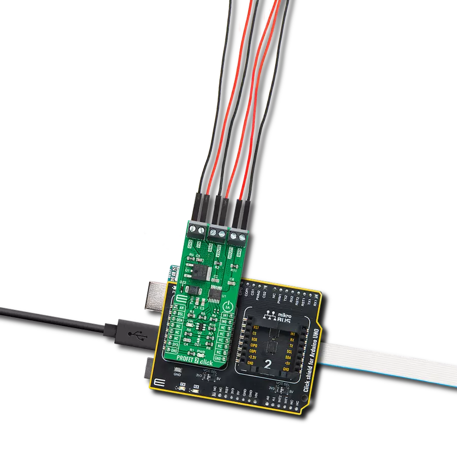
Click Shield for Arduino UNO has two proprietary mikroBUS™ sockets, allowing all the Click board™ devices to be interfaced with the Arduino UNO board without effort. The Arduino Uno, a microcontroller board based on the ATmega328P, provides an affordable and flexible way for users to try out new concepts and build prototypes with the ATmega328P microcontroller from various combinations of performance, power consumption, and features. The Arduino Uno has 14 digital input/output pins (of which six can be used as PWM outputs), six analog inputs, a 16 MHz ceramic resonator (CSTCE16M0V53-R0), a USB connection, a power jack, an ICSP header, and reset button. Most of the ATmega328P microcontroller pins are brought to the IO pins on the left and right edge of the board, which are then connected to two existing mikroBUS™ sockets. This Click Shield also has several switches that perform functions such as selecting the logic levels of analog signals on mikroBUS™ sockets and selecting logic voltage levels of the mikroBUS™ sockets themselves. Besides, the user is offered the possibility of using any Click board™ with the help of existing bidirectional level-shifting voltage translators, regardless of whether the Click board™ operates at a 3.3V or 5V logic voltage level. Once you connect the Arduino UNO board with our Click Shield for Arduino UNO, you can access hundreds of Click boards™, working with 3.3V or 5V logic voltage levels.

Used MCU Pins
mikroBUS™ mapper
Take a closer look
Click board™ Schematic

Step by step
Project assembly

Start by selecting your development board and Click board™. Begin with the Arduino UNO Rev3 as your development board.


Track your results in real time
Application Output
1. Application Output - In Debug mode, the 'Application Output' window enables real-time data monitoring, offering direct insight into execution results. Ensure proper data display by configuring the environment correctly using the provided tutorial.

2. UART Terminal - Use the UART Terminal to monitor data transmission via a USB to UART converter, allowing direct communication between the Click board™ and your development system. Configure the baud rate and other serial settings according to your project's requirements to ensure proper functionality. For step-by-step setup instructions, refer to the provided tutorial.

3. Plot Output - The Plot feature offers a powerful way to visualize real-time sensor data, enabling trend analysis, debugging, and comparison of multiple data points. To set it up correctly, follow the provided tutorial, which includes a step-by-step example of using the Plot feature to display Click board™ readings. To use the Plot feature in your code, use the function: plot(*insert_graph_name*, variable_name);. This is a general format, and it is up to the user to replace 'insert_graph_name' with the actual graph name and 'variable_name' with the parameter to be displayed.

Software Support
Library Description
This library contains API for SolidSwitch 2 Click driver.
Key functions:
solidswitch2_write_registerThis function writes a desired data to the selected register by using SPI serial interface.solidswitch2_toggle_in0_pinThis function toggles the IN0 pin logic state.solidswitch2_toggle_in1_pinThis function toggles the IN1 pin logic state.
Open Source
Code example
The complete application code and a ready-to-use project are available through the NECTO Studio Package Manager for direct installation in the NECTO Studio. The application code can also be found on the MIKROE GitHub account.
/*!
 * @file main.c
 * @brief SolidSwitch 2 Click example
 *
 * # Description
 * This example demonstrates the use of SolidSwitch 2 Click board by controlling the output state.
 *
 * The demo application is composed of two sections :
 *
 * ## Application Init
 * Initializes the driver and performs the Click default configuration which maps outputs as follows:
 * OUT2   - IN0,
 * OUT3   - IN1,
 * OUT4-5 - PWM GEN,
 * OUT6-7 - PWM LED.
 *
 * ## Application Task
 * Changes the PWM GEN (max to min) and PWM LED (min to max) duty cycle and toggles the IN0 and IN1
 * pins every 250ms. The duty cycle values and INx toggle messages will be displayed on the USB UART.
 *
 * @author Stefan Filipovic
 *
 */

#include "board.h"
#include "log.h"
#include "solidswitch2.h"

static solidswitch2_t solidswitch2;
static log_t logger;

void application_init ( void )
{
    log_cfg_t log_cfg;  /**< Logger config object. */
    solidswitch2_cfg_t solidswitch2_cfg;  /**< Click config object. */

    /**
     * Logger initialization.
     * Default baud rate: 115200
     * Default log level: LOG_LEVEL_DEBUG
     * @note If USB_UART_RX and USB_UART_TX
     * are defined as HAL_PIN_NC, you will
     * need to define them manually for log to work.
     * See @b LOG_MAP_USB_UART macro definition for detailed explanation.
     */
    LOG_MAP_USB_UART( log_cfg );
    log_init( &logger, &log_cfg );
    log_info( &logger, " Application Init " );

    // Click initialization.
    solidswitch2_cfg_setup( &solidswitch2_cfg );
    SOLIDSWITCH2_MAP_MIKROBUS( solidswitch2_cfg, MIKROBUS_1 );
    if ( SPI_MASTER_ERROR == solidswitch2_init( &solidswitch2, &solidswitch2_cfg ) )
    {
        log_error( &logger, " Communication init." );
        for ( ; ; );
    }

    if ( SOLIDSWITCH2_ERROR == solidswitch2_default_cfg ( &solidswitch2 ) )
    {
        log_error( &logger, " Default configuration." );
        for ( ; ; );
    }

    log_info( &logger, " Application Task " );
}

void application_task ( void )
{
    for ( uint16_t duty_cycle = SOLIDSWITCH2_MIN_DUTY_CYCLE; duty_cycle <= SOLIDSWITCH2_MAX_DUTY_CYCLE; duty_cycle += 5 )
    {
        if ( SOLIDSWITCH2_OK == solidswitch2_write_register ( &solidswitch2, SOLIDSWITCH2_REG_PWM_GEN_DC,
                                                              ( uint8_t ) ( SOLIDSWITCH2_MAX_DUTY_CYCLE - duty_cycle ) ) )
        {
            log_printf ( &logger, " PWM GEN DC: %u\r\n", ( SOLIDSWITCH2_MAX_DUTY_CYCLE - duty_cycle ) );
        }
        if ( SOLIDSWITCH2_OK == solidswitch2_write_register ( &solidswitch2, SOLIDSWITCH2_REG_PWM_LED_DC, ( uint8_t ) duty_cycle ) )
        {
            log_printf ( &logger, " PWM LED DC: %u\r\n", duty_cycle );
        }
        solidswitch2_toggle_in0_pin ( &solidswitch2 );
        log_printf ( &logger, " Toggle IN0 pin\r\n" );
        solidswitch2_toggle_in1_pin ( &solidswitch2 );
        log_printf ( &logger, " Toggle IN1 pin\r\n\n" );
        Delay_ms ( 250 );
    }
}

int main ( void )
{
    /* Do not remove this line or clock might not be set correctly. */
    #ifdef PREINIT_SUPPORTED
    preinit();
    #endif

    application_init( );

    for ( ; ; )
    {
        application_task( );
    }

    return 0;
}

// ------------------------------------------------------------------------ END
Additional Support
Resources
Category:Power Switch