Say hello to clean air with ZMOD4510 and ATmega6450
Guardians of Freshness: Our solution, your healthier reality

Published Aug 30, 2023
Click board™
Air quality 8 Click
Dev. board
UNI-DS v8
Compiler
NECTO Studio
MCU
ATmega6450
Designed to address the growing concern of air pollution, our monitor solution acts as a guardian, ensuring the air you breathe is of the highest quality
A
A
Hardware Overview
How does it work?
Air quality 8 Click is based on the ZMOD4510, a pre-calibrated digital sensor designed for reliable indoor and outdoor air quality detection from Renesas. This sensor comes with selective ozone measurement capabilities (NO2 and O3) and allows improved energy efficiency with less than 23mW of power consumption in continuous operation without compromising air quality. It also features electrical and gas calibration, proven MOx material, a digital interface, siloxane resistance, high sensitivity, and long-term stability, allowing ppb detection limits. It covers extended operating humidity and temperature ranges from 5 to 90%RH and from -20°C to 50°C with ozone and nitrogen dioxide measurement ranges from 20 to 500ppb. The ZMOD4510 has a gas-sense element consisting of a heater element on a silicon-based MEMS structure, a metal-oxide (MOx) chemiresistor, and a CMOS signal conditioning IC that controls the sensor temperature and
measures the MOx resistance, which is a function of the gas concentration. It has two operational modes. The first mode of operation allows a general measurement of Air Quality, including the non-selective measurement of nitrogen dioxide (NO2) and ozone (O3). The second mode of operation allows the selective measurement of ozone (O3) featuring Ultra-Low Power with an average consumption of 0.2mW during its fast sample rate of 2 seconds. It detects typical gases based on studies and international standards for outdoor air quality and uses a sequence of applied temperatures to sample the air and report an Air Quality Index (AQI). The sensor does not require an active or direct airflow onto the sensor module because diffusion of ambient gas does not limit the sensor response time. The ZMOD4510 can also detect safety-relevant gases; however, the sensor module is not designed to detect these interferants reliably. Therefore, it is not approved
for use in safety-critical or life-protecting applications. Air quality 8 Click communicates with MCU using the standard I2C 2-Wire interface to read data and configure settings, supporting Standard Mode operation with a clock frequency of 100kHz and Fast Mode up to 400kHz. In addition, it also possesses other features such as a reset pin routed to the RST pin on the mikroBUS™ socket, which with a low logic level puts the module into a Reset state, an additional interrupt signal routed on the INT pin of the mikroBUS™ socket labeled as INT, indicating the status of measurement process itself. This Click board™ can be operated only with a 3.3V logic voltage level. The board must perform appropriate logic voltage level conversion before using MCUs with different logic levels. Also, it comes equipped with a library containing functions and an example code that can be used as a reference for further development.


Features overview
Development board
UNI-DS v8 is a development board specially designed for the needs of rapid development of embedded applications. It supports a wide range of microcontrollers, such as different STM32, Kinetis, TIVA, CEC, MSP, PIC, dsPIC, PIC32, and AVR MCUs regardless of their number of pins, and a broad set of unique functions, such as the first-ever embedded debugger/programmer over WiFi. The development board is well organized and designed so that the end-user has all the necessary elements, such as switches, buttons, indicators, connectors, and others, in one place. Thanks to innovative manufacturing technology, UNI-DS v8 provides a fluid and immersive working experience, allowing access anywhere and under any
circumstances at any time. Each part of the UNI-DS v8 development board contains the components necessary for the most efficient operation of the same board. An advanced integrated CODEGRIP programmer/debugger module offers many valuable programming/debugging options, including support for JTAG, SWD, and SWO Trace (Single Wire Output)), and seamless integration with the Mikroe software environment. Besides, it also includes a clean and regulated power supply module for the development board. It can use a wide range of external power sources, including a battery, an external 12V power supply, and a power source via the USB Type-C (USB-C) connector. Communication options such as USB-UART, USB
HOST/DEVICE, CAN (on the MCU card, if supported), and Ethernet is also included. In addition, it also has the well-established mikroBUS™ standard, a standardized socket for the MCU card (SiBRAIN standard), and two display options for the TFT board line of products and character-based LCD. UNI-DS v8 is an integral part of the Mikroe ecosystem for rapid development. Natively supported by Mikroe software tools, it covers many aspects of prototyping and development thanks to a considerable number of different Click boards™ (over a thousand boards), the number of which is growing every day.

Microcontroller Overview
MCU Card / MCU
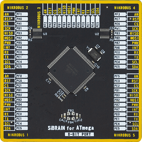
Type
8th Generation
Architecture
AVR
MCU Memory (KB)
64
Silicon Vendor
Microchip
Pin count
100
RAM (Bytes)
4096
Used MCU Pins
mikroBUS™ mapper
Take a closer look
Click board™ Schematic

Step by step
Project assembly

Start by selecting your development board and Click board™. Begin with the UNI-DS v8 as your development board.


Software Support
Library Description
This library contains API for Air Quality 8 Click driver.
Key functions:
airquality8_calc_oaq- Air Quality 8 calculates AQI functionairquality8_read_rmox- Air Quality 8 calculate rmox resistance functionairquality8_start_measurement- Air Quality 8 start measurement function
Open Source
Code example
The complete application code and a ready-to-use project are available through the NECTO Studio Package Manager for direct installation in the NECTO Studio. The application code can also be found on the MIKROE GitHub account.
/*!
 * @file main.c
 * @brief AirQuality8 Click example
 *
 * # Description
 * This library contains API for Air Quality 8 Click driver.
 * The library initializes and defines the I2C bus drivers
 * to write and read data from registers.
 * The library also includes a function for configuring sensor and measurement,
 * read and calculate mox resistance ( RMOX ) and air quality index ( AQI ), etc.
 *
 * The demo application is composed of two sections :
 *
 * ## Application Init
 * Initialization of I2C module and log UART, and additional pins.
 * After the driver inits and executes a default configuration,
 * the app read product ID and configuration parameters,
 * initializes the sensor and measurement.
 *
 * ## Application Task
 * This is an example that demonstrates the use of the Air Quality 8 Click board™.
 * In this example, the app performs the start of the measurement,
 * reads an array of the 15 mox resistances measurements ( RMOX ),
 * and calculates the air quality index ( AQI ), the app also, displays if an error occurs.
 * Results are being sent to the Usart Terminal where you can track their changes.
 *
 * ## Additional Function
 * - static void display_error ( void )
 *
 * @author Nenad Filipovic
 *
 */

#include "board.h"
#include "log.h"
#include "airquality8.h"

static airquality8_t airquality8;
static log_t logger;
static uint16_t mox_lr;
static uint16_t mox_er;
static uint8_t status_flag;

static void display_error ( void )
{
    if ( status_flag == AIRQUALITY8_ERROR_INIT_OUT_OF_RANGE )
    {
        log_printf( &logger, " The initialize value is out of range.\r\n" );
    }

    if ( status_flag == AIRQUALITY8_ERROR_GAS_TIMEOUT )
    {
        log_printf( &logger, " The operation took too long.\r\n" );
    }

    if ( status_flag == AIRQUALITY8_ERROR_I2C )
    {
        log_printf( &logger, " Failure in i2c communication.\r\n" );
    }

    if ( status_flag == AIRQUALITY8_ERROR_SENSOR_UNSUPPORTED )
    {
        log_printf( &logger, " Sensor is not supported with this firmware.\r\n" );
    }

    if ( status_flag == AIRQUALITY8_ERROR_CONFIG_MISSING )
    {
        log_printf( &logger, " There is no pointer to a valid configuration.\r\n" );
    }

    if ( status_flag == AIRQUALITY8_ERROR_SENSOR )
    {
        log_printf( &logger, " Sensor malfunction.\r\n" );
    }
}

void application_init ( void )
{
    log_cfg_t log_cfg;  /**< Logger config object. */
    airquality8_cfg_t airquality8_cfg;  /**< Click config object. */

    /**
     * Logger initialization.
     * Default baud rate: 115200
     * Default log level: LOG_LEVEL_DEBUG
     * @note If USB_UART_RX and USB_UART_TX
     * are defined as HAL_PIN_NC, you will
     * need to define them manually for log to work.
     * See @b LOG_MAP_USB_UART macro definition for detailed explanation.
     */
    LOG_MAP_USB_UART( log_cfg );
    log_init( &logger, &log_cfg );
    log_info( &logger, " Application Init " );

    // Click initialization.
    airquality8_cfg_setup( &airquality8_cfg );
    AIRQUALITY8_MAP_MIKROBUS( airquality8_cfg, MIKROBUS_1 );
    if ( I2C_MASTER_ERROR == airquality8_init( &airquality8, &airquality8_cfg ) )
    {
        log_error( &logger, " Communication init." );
        for ( ; ; );
    }

    if ( AIRQUALITY8_ERROR == airquality8_default_cfg ( &airquality8 ) )
    {
        log_error( &logger, " Default configuration." );
        for ( ; ; );
    }
    Delay_ms ( 100 );

    static uint8_t cfg_data[ 6 ];
    static uint8_t prod_data[ 5 ];
    static uint16_t pid;

    airquality8_get_sensor_info( &airquality8, &cfg_data[ 0 ], &prod_data[ 0 ], &pid );

    if ( pid != AIRQUALITY8_PRODUCT_ID )
    {
        status_flag = AIRQUALITY8_ERROR_I2C;
        display_error( );
        for ( ; ; );
    }
    Delay_ms ( 100 );

    log_printf( &logger, "---------------------------\r\n" );
    log_printf( &logger, " Product ID : 0x%.2X  \r\n", pid );
    Delay_ms ( 100 );

    airquality8_init_sensor( &airquality8, &mox_lr, &mox_er );
    Delay_ms ( 10 );

    airquality8_init_measurement( &airquality8 );
    Delay_ms ( 10 );

    log_printf( &logger, "---------------------------\r\n" );
    log_info( &logger, " Application Task " );
    log_printf( &logger, "---------------------------\r\n" );
    log_printf( &logger, "      Air Quality Index\r\n" );
    log_printf( &logger, "- - - - - - - - - - - - - -\r\n" );
    Delay_ms ( 100 );
}

void application_task ( void )
{
    static uint8_t status_data;
    static float rmox;
    static float rmox_seq[ 15 ];
    static float aqi;

    status_flag = airquality8_start_measurement( &airquality8 );

    airquality8_get_status( &airquality8, &status_data );
    Delay_ms ( 10 );

    while ( ( status_data & AIRQUALITY8_STATUS_LAST_SEQ_STEP_MASK ) != AIRQUALITY8_OK )
    {
        airquality8_get_status( &airquality8, &status_data );
        Delay_ms ( 10 );
    }

    for ( uint8_t n_cnt = 0; n_cnt < 15; n_cnt++ )
    {
        status_flag = airquality8_read_rmox( &airquality8, &rmox, mox_lr, mox_er );
        rmox_seq[ n_cnt ] = rmox;
        Delay_ms ( 100 );

        if ( status_flag != AIRQUALITY8_OK )
        {
            display_error( );
        }
    }

    aqi = airquality8_calc_oaq( rmox_seq, AIRQUALITY8_RCDA_STRATEGY_ADJ, AIRQUALITY8_GAS_DETECTION_STRATEGY_AUTO );
    log_printf( &logger, " \tAQI : %.3f \r\n", aqi );
    log_printf( &logger, "---------------------------\r\n" );
    Delay_ms ( 1000 );
}

int main ( void )
{
    /* Do not remove this line or clock might not be set correctly. */
    #ifdef PREINIT_SUPPORTED
    preinit();
    #endif

    application_init( );

    for ( ; ; )
    {
        application_task( );
    }

    return 0;
}

// ------------------------------------------------------------------------ END


