Create complex waveforms with AD9106 and PIC18LF45K50
Rock the Waves
Published May 27, 2023
Click board™
Waveform 4 Click
Dev. board
EasyPIC v7a
Compiler
NECTO Studio
MCU
PIC18LF45K50
Unleash your creativity with a cutting-edge waveform generator
A
A
Hardware Overview
How does it work?
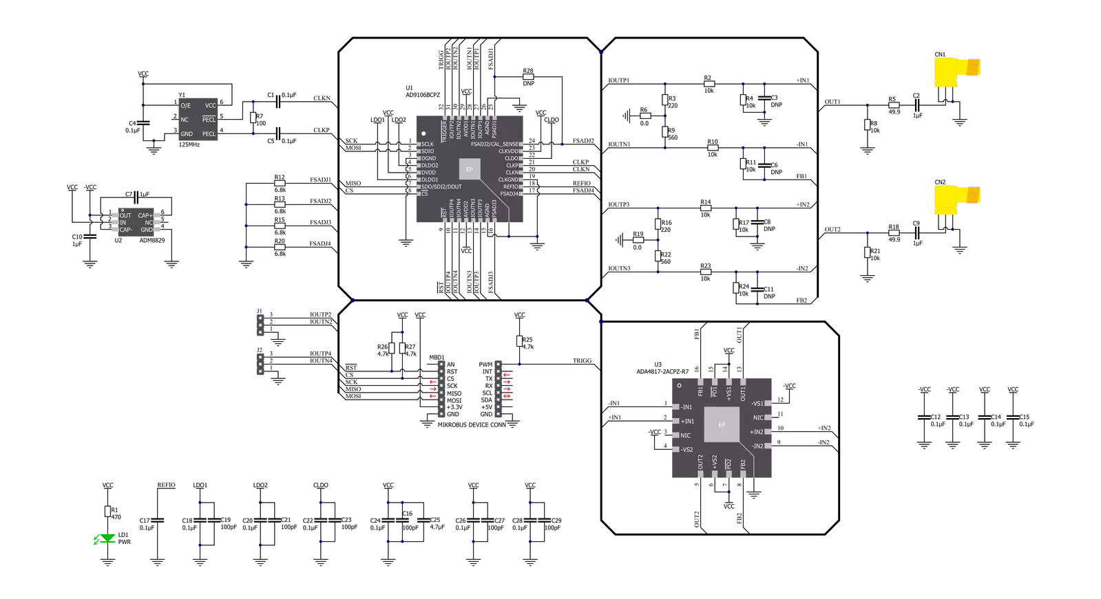
Waveform 4 Click is based on the AD9106, a high-performance, quad digital-to-analog converter (DAC) integrating on-chip pattern memory for complex waveform generation with a direct digital synthesizer (DDS) from Analog Devices. The DDS is a 12-bit output, up to 180 MHz master clock sinewave generator with a 24-bit tuning word allowing 10.8 Hz/LSB frequency resolution. This Click board™, by default, uses an onboard 125 MHz crystal oscillator as a clock source, which is also the maximum output frequency for this board. The high-speed, high-dynamic-range, multichannel complex waveforms generated by AD9106 are suitable for applications such as ultrasound transducer excitation, medical instrumentation, portable instrumentation, signal generators, and arbitrary waveform generators. Pattern data can include directly generated SRAM-stored waveforms, DDS outputs amplitude-modulated by SRAM, or DDS frequency tuning words from SRAM providing chirp or frequency shift keying (FSK) modulation. An internal pattern-control state machine allows the user to program the pattern period for all D/A converters, the start delay within the pattern period for the signal
output on each D/A converter channel, and the repetition rate of the pattern. The generation of a pattern is configurable via TRG routed to the PWM pin of the mikroBUS™ socket. A falling edge on the TRG pin starts generating a pattern, while the rising edge represents a request to terminate pattern generation. The AD9106 has a single frequency output and independently programmable phase shift outputs for each of the four integrated DACs. Besides, gain adjustment factors and offset adjustments are applied to the digital signals on their way into the four DACs. The two DAC outputs of the AD9106 are filtered by an RC network and then amplified via ADA4817-2, an operational amplifier that combines new architecture for FET input operational amplifiers with the eXFCB process from Analog Devices, resulting in an outstanding combination of speed and low noise. The other two outputs, without amplification, were routed on onboard headers labeled as I2 and I4. In addition to the positive supply voltage requirement, the ADA4817-2 amplifier also has a negative supply voltage, achieved by the ADM8829, a charge-pump voltage inverter used to generate a negative supply from a positive input
from Analog Devices. The output signal from the ADA4817-2 follows two paths. One path is routed to an output connector labeled OUT1, while the other is routed to an output connector labeled OUT3. On these connectors, the AD9106 can generate two types of signal patterns under the control of its programmable pattern generator: periodic pulse train waveforms that repeat indefinitely or periodic pulse train waveforms that repeat a finite number of times. This Click board™ communicates with MCU through a standard SPI interface to program the internal registers for complete control of the AD9106. Besides, it possesses additional functionality, such as a reset function implemented and routed at the RST pin of the mikroBUS™ socket, which resets all registers of the AD9106 to their default state. This Click board™ can only be operated with a 3.3V logic voltage level. The board must perform appropriate logic voltage level conversion before using MCUs with different logic levels. However, the Click board™ comes equipped with a library containing functions and an example code that can be used as a reference for further development.

Features overview
Development board
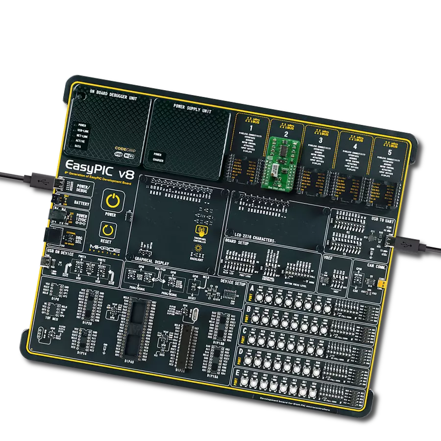
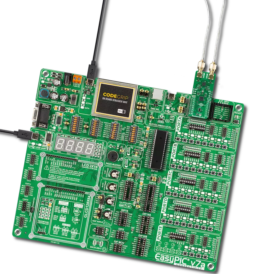
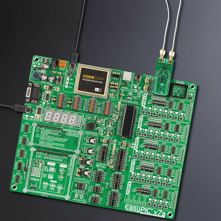
EasyPIC v7a is the seventh generation of PIC development boards specially designed for the needs of rapid development of embedded applications. It supports a wide range of 8-bit PIC microcontrollers from Microchip and has a broad set of unique functions, such as the first-ever embedded debugger/programmer over USB-C. The development board is well organized and designed so that the end-user has all the necessary elements in one place, such as switches, buttons, indicators, connectors, and others. With four different connectors for each port, EasyPIC v7a allows you to connect accessory boards, sensors, and custom electronics more efficiently than ever. Each part of the EasyPIC v7a development board
contains the components necessary for the most efficient operation of the same board. In addition to the advanced integrated CODEGRIP programmer/debugger module, which offers many valuable programming/debugging options and seamless integration with the Mikroe software environment, the board also includes a clean and regulated power supply module for the development board. It can use various external power sources, including an external 12V power supply, 7-23V AC or 9-32V DC via DC connector/screw terminals, and a power source via the USB Type-C (USB-C) connector. Communication options such as USB-UART and RS-232 are also included, alongside the well-
established mikroBUS™ standard, three display options (7-segment, graphical, and character-based LCD), and several different DIP sockets. These sockets cover a wide range of 8-bit PIC MCUs, from PIC10F, PIC12F, PIC16F, PIC16Enh, PIC18F, PIC18FJ, and PIC18FK families. EasyPIC v7a is an integral part of the Mikroe ecosystem for rapid development. Natively supported by Mikroe software tools, it covers many aspects of prototyping and development thanks to a considerable number of different Click boards™ (over a thousand boards), the number of which is growing every day.

Microcontroller Overview
MCU Card / MCU
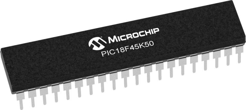
Architecture
PIC
MCU Memory (KB)
32
Silicon Vendor
Microchip
Pin count
40
RAM (Bytes)
2048
Used MCU Pins
mikroBUS™ mapper
Take a closer look
Click board™ Schematic
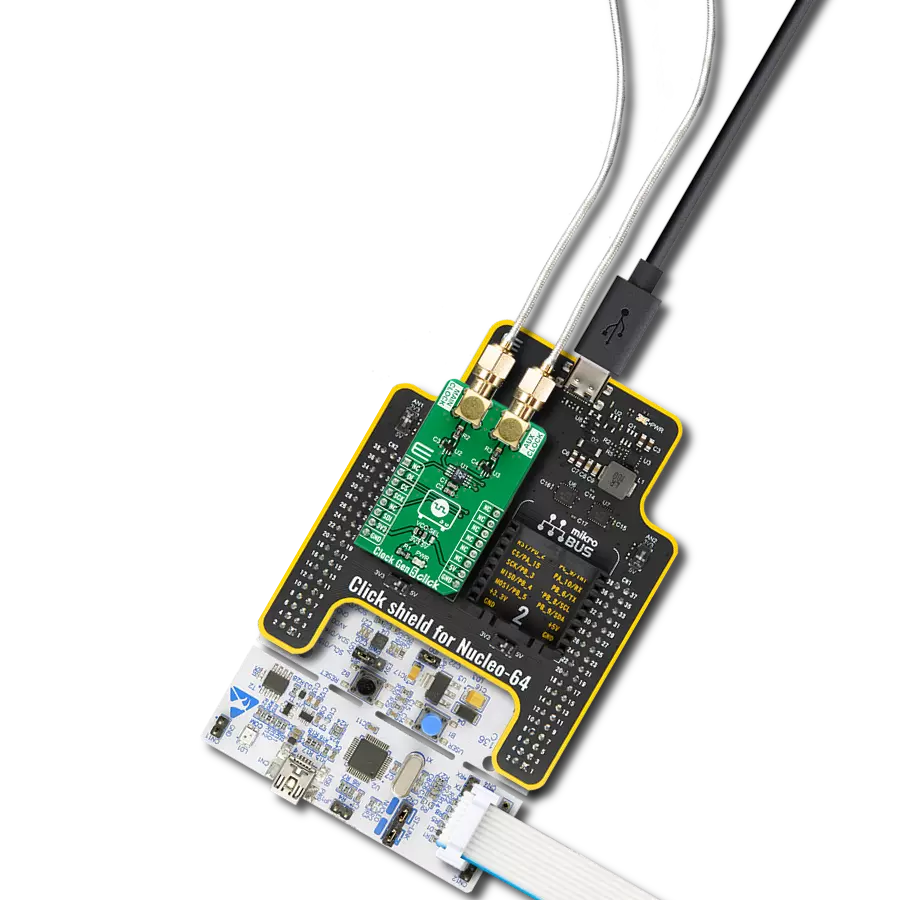
Step by step
Project assembly

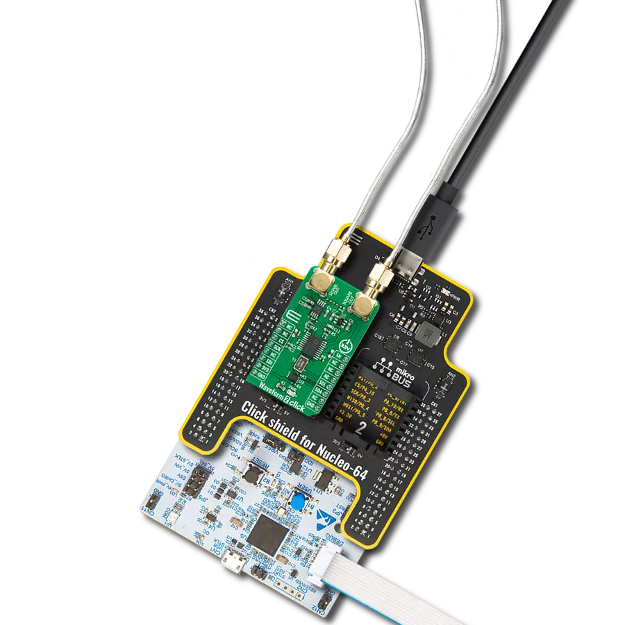
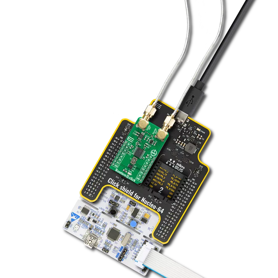
Start by selecting your development board and Click board™. Begin with the EasyPIC v7a as your development board.


Track your results in real time
Application Output
1. Application Output - In Debug mode, the 'Application Output' window enables real-time data monitoring, offering direct insight into execution results. Ensure proper data display by configuring the environment correctly using the provided tutorial.

2. UART Terminal - Use the UART Terminal to monitor data transmission via a USB to UART converter, allowing direct communication between the Click board™ and your development system. Configure the baud rate and other serial settings according to your project's requirements to ensure proper functionality. For step-by-step setup instructions, refer to the provided tutorial.

3. Plot Output - The Plot feature offers a powerful way to visualize real-time sensor data, enabling trend analysis, debugging, and comparison of multiple data points. To set it up correctly, follow the provided tutorial, which includes a step-by-step example of using the Plot feature to display Click board™ readings. To use the Plot feature in your code, use the function: plot(*insert_graph_name*, variable_name);. This is a general format, and it is up to the user to replace 'insert_graph_name' with the actual graph name and 'variable_name' with the parameter to be displayed.

Software Support
Library Description
This library contains API for Waveform 4 Click driver.
Key functions:
waveform4_set_frequencyThis function sets the sine and cosine (DDS) waves output frequency.waveform4_set_gainThis function sets the gain level of a desired channel.waveform4_set_wave_outputThis function sets a desired output signal wave to the selected channel.
Open Source
Code example
The complete application code and a ready-to-use project are available through the NECTO Studio Package Manager for direct installation in the NECTO Studio. The application code can also be found on the MIKROE GitHub account.
/*!
 * @file main.c
 * @brief Waveform4 Click example
 *
 * # Description
 * This example demonstrates the use of Waveform 4 Click board.
 *
 * The demo application is composed of two sections :
 *
 * ## Application Init
 * Initializes the driver and performs the Click default configuration which
 * resets the registers and sets the sine wave output with default gain and
 * default frequency for all channels. After that it displays the list of
 * supported commands on the USB UART.
 *
 * ## Application Task
 * Depending on the command character received from USB UART it changes the
 * signal frequency, gain or wave of the selected channel.
 *
 * @author Stefan Filipovic
 *
 */

#include "board.h"
#include "log.h"
#include "waveform4.h"

static waveform4_t waveform4;
static log_t logger;

#define GAIN_STEP 0.05  // Gain step, used for increase/decrease gain commands.
#define FREQ_STEP 100   // Frequency step, used for increase/decrease frequency commands.

uint32_t freq = WAVEFORM4_DEFAULT_FREQUENCY;
float gain = WAVEFORM4_DEFAULT_GAIN;
uint8_t channel = WAVEFORM4_CHANNEL_1;
uint8_t wave = WAVEFORM4_WAVE_SINE;

/**
 * @brief Waveform 4 display commands function.
 * @details This function displays the list of supported commands on the USB UART.
 * @return None.
 * @note None.
 */
void waveform4_display_commands ( void );

/**
 * @brief Waveform 4 parse command function.
 * @details This function checks if the input command is supported and executes it.
 * @param[in] command : Command input, for more details refer to @b waveform4_display_commands function.
 * @return @li @c  0 - Success,
 *         @li @c -1 - Wrong command or command is not executed properly.
 *
 * See #err_t definition for detailed explanation.
 * @note None.
 */
err_t waveform4_parse_command ( uint8_t command );

void application_init ( void )
{
    log_cfg_t log_cfg;  /**< Logger config object. */
    waveform4_cfg_t waveform4_cfg;  /**< Click config object. */

    /**
     * Logger initialization.
     * Default baud rate: 115200
     * Default log level: LOG_LEVEL_DEBUG
     * @note If USB_UART_RX and USB_UART_TX
     * are defined as HAL_PIN_NC, you will
     * need to define them manually for log to work.
     * See @b LOG_MAP_USB_UART macro definition for detailed explanation.
     */
    LOG_MAP_USB_UART( log_cfg );
    log_init( &logger, &log_cfg );
    log_info( &logger, " Application Init " );

    // Click initialization.
    waveform4_cfg_setup( &waveform4_cfg );
    WAVEFORM4_MAP_MIKROBUS( waveform4_cfg, MIKROBUS_1 );
    if ( SPI_MASTER_ERROR == waveform4_init( &waveform4, &waveform4_cfg ) )
    {
        log_error( &logger, " Communication init." );
        for ( ; ; );
    }

    if ( WAVEFORM4_ERROR == waveform4_default_cfg ( &waveform4 ) )
    {
        log_error( &logger, " Default configuration." );
        for ( ; ; );
    }

    waveform4_display_commands ( );
    log_info( &logger, " Application Task " );
}

void application_task ( void )
{
    uint8_t command = 0;
    if ( log_read ( &logger, &command, 1 ) > 0 )
    {
        waveform4_parse_command ( command );
    }
}

int main ( void )
{
    /* Do not remove this line or clock might not be set correctly. */
    #ifdef PREINIT_SUPPORTED
    preinit();
    #endif

    application_init( );

    for ( ; ; )
    {
        application_task( );
    }

    return 0;
}

void waveform4_display_commands ( void )
{
    log_printf( &logger, "-------------------------------------------\r\n" );
    log_info( &logger, "- UART commands list -\r\n" );
    log_printf( &logger, "'+' - Increase frequency.\r\n" );
    log_printf( &logger, "'-' - Decrease frequency.\r\n" );
    log_printf( &logger, "'G' - Increase gain.\r\n" );
    log_printf( &logger, "'g' - Decrease gain.\r\n" );
    log_printf( &logger, "'S' or 's' - Select sine wave output.\r\n" );
    log_printf( &logger, "'C' or 'c' - Select cosine wave output.\r\n" );
    log_printf( &logger, "'T' or 't' - Select triangle wave output.\r\n" );
    log_printf( &logger, "'P' or 'p' - Select positive sawtooth wave output.\r\n" );
    log_printf( &logger, "'N' or 'n' - Select negative sawtooth wave output.\r\n" );
    log_printf( &logger, "'1' - Select channel 1.\r\n" );
    log_printf( &logger, "'2' - Select channel 2.\r\n" );
    log_printf( &logger, "'3' - Select channel 3.\r\n" );
    log_printf( &logger, "'4' - Select channel 4.\r\n" );
    log_printf( &logger, "'L' or 'l' - Display commands list.\r\n" );
    log_printf( &logger, "-------------------------------------------\r\n" );
}

err_t waveform4_parse_command ( uint8_t command )
{
    switch( command )
    {
        case '+':
        {
            freq += FREQ_STEP;
            if ( freq > WAVEFORM4_MASTER_CLOCK )
            {
                freq = WAVEFORM4_MASTER_CLOCK;
            }
            log_printf( &logger, "Frequency increased: %lu Hz\r\n", freq );
            return waveform4_set_frequency ( &waveform4, freq );
        }
        case '-':
        {
            freq -= FREQ_STEP;
            if ( freq > WAVEFORM4_MASTER_CLOCK )
            {
                freq = 0;
            }
            log_printf( &logger, "Frequency decreased: %lu Hz\r\n", freq );
            return waveform4_set_frequency ( &waveform4, freq );
        }
        case 'G':
        {
            gain += GAIN_STEP;
            if ( gain > WAVEFORM4_GAIN_MAX )
            {
                gain = WAVEFORM4_GAIN_MAX;
            }
            log_printf( &logger, "Gain increased: %.3f\r\n", gain );
            return waveform4_set_gain ( &waveform4, channel, gain );
        }
        case 'g':
        {
            gain -= GAIN_STEP;
            if ( gain < WAVEFORM4_GAIN_MIN )
            {
                gain = WAVEFORM4_GAIN_MIN;
            }
            log_printf( &logger, "Gain decreased: %.3f\r\n", gain );
            return waveform4_set_gain ( &waveform4, channel, gain );
        }
        case 'S': case 's':
        {
            wave = WAVEFORM4_WAVE_SINE;
            log_printf( &logger, "Sine wave selected.\r\n" );
            return waveform4_set_wave_output ( &waveform4, channel, wave );
        }
        case 'C': case 'c':
        {
            wave = WAVEFORM4_WAVE_COSINE;
            log_printf( &logger, "Cosine wave selected.\r\n" );
            return waveform4_set_wave_output ( &waveform4, channel, wave );
        }
        case 'T': case 't':
        {
            wave = WAVEFORM4_WAVE_TRIANGLE;
            log_printf( &logger, "Triangle wave selected.\r\n" );
            return waveform4_set_wave_output ( &waveform4, channel, wave );
        }
        case 'P': case 'p':
        {
            wave = WAVEFORM4_WAVE_POSITIVE_SAWTOOTH;
            log_printf( &logger, "Positive sawtooth wave selected.\r\n" );
            return waveform4_set_wave_output ( &waveform4, channel, wave );
        }
        case 'N': case 'n':
        {
            wave = WAVEFORM4_WAVE_NEGATIVE_SAWTOOTH;
            log_printf( &logger, "Negative sawtooth wave selected.\r\n" );
            return waveform4_set_wave_output ( &waveform4, channel, wave );
        }
        case '1':
        {
            channel = WAVEFORM4_CHANNEL_1;
            log_printf( &logger, "Channel 1 selected.\r\n" );
            return waveform4_set_wave_output ( &waveform4, channel, wave );
        }
        case '2':
        {
            channel = WAVEFORM4_CHANNEL_2;
            log_printf( &logger, "Channel 2 selected.\r\n" );
            return waveform4_set_wave_output ( &waveform4, channel, wave );
        }
        case '3':
        {
            channel = WAVEFORM4_CHANNEL_3;
            log_printf( &logger, "Channel 3 selected.\r\n" );
            return waveform4_set_wave_output ( &waveform4, channel, wave );
        }
        case '4':
        {
            channel = WAVEFORM4_CHANNEL_4;
            log_printf( &logger, "Channel 4 selected.\r\n" );
            return waveform4_set_wave_output ( &waveform4, channel, wave );
        }
        case 'L': case 'l':
        {
            waveform4_display_commands ( );
            return WAVEFORM4_OK;
        }
        default :
        {
            log_error( &logger, "Wrong command." );
            return WAVEFORM4_ERROR;
        }
    }
}

// ------------------------------------------------------------------------ END
Additional Support
Resources
Category:Clock generator