Enhance your safety by monitoring hydrogen gas leaks using MQ-8 and PIC18LF45K22
Precise hydrogen sensing for all

Published Jun 20, 2023
Click board™
HYDROGEN Click
Dev. board
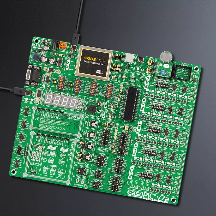
EasyPIC v7a
Compiler
NECTO Studio
MCU
PIC18LF45K22
By providing early detection of hydrogen leaks, this detection solution helps prevent the potential risks of fire, explosions, and asphyxiation, safeguarding the well-being of individuals and protecting property
A
A
Hardware Overview
How does it work?
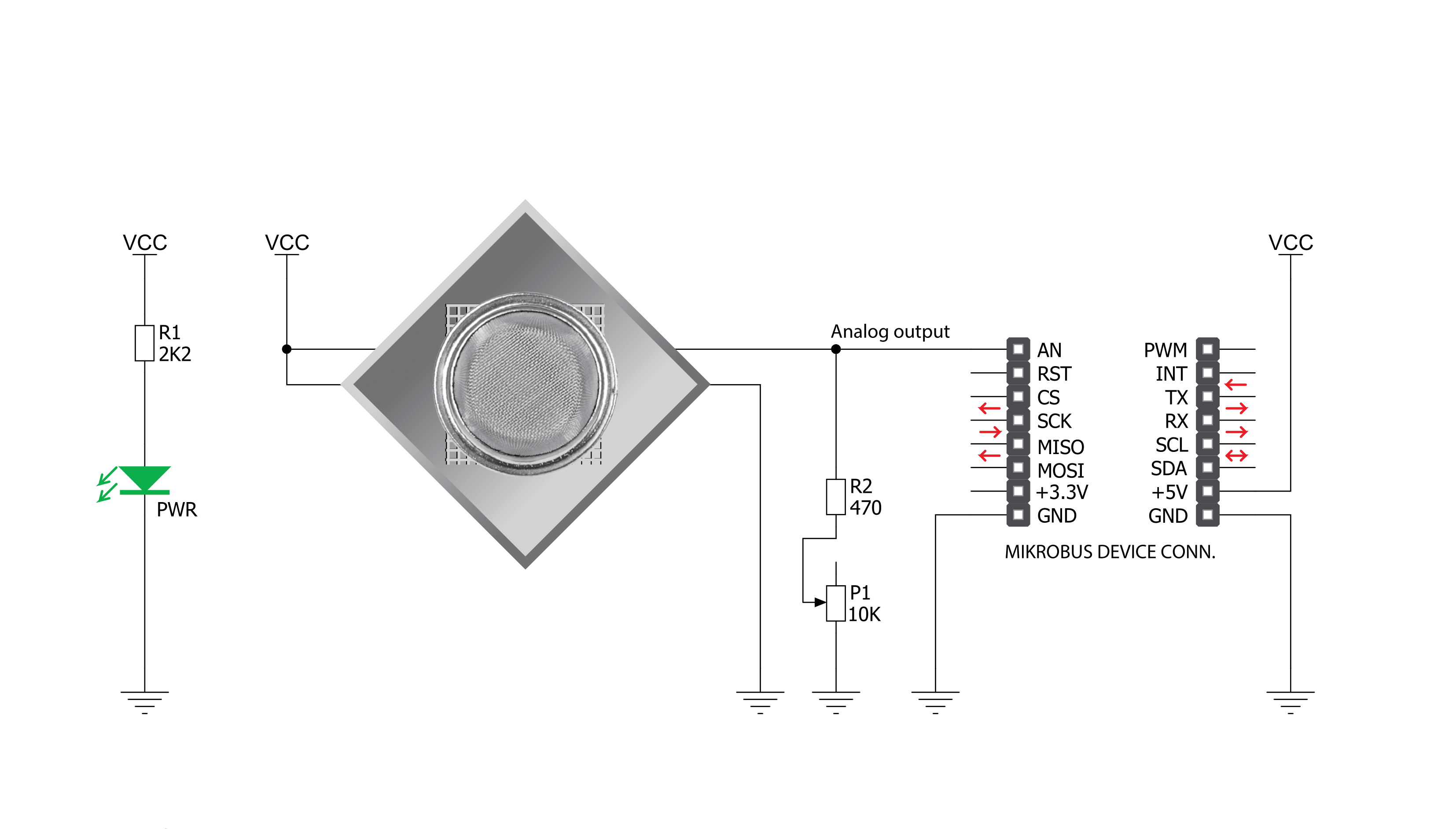
Hydrogen Click is based on the MQ-8, a hydrogen (H2) sensor from Zhengzhou Winsen Electronics Technology, which detects hydrogen's presence and concentration in the air. The gas sensing layer on the MQ-8 sensor unit is made of Tin dioxide (SnO2), which has lower conductivity in clean air. The conductivity increases as the levels of hydrogen rise. It has a high sensitivity to hydrogen in a wide range suitable for detecting it in concentrations from 100 to 10.000ppm. Besides a
binary indication of the presence of hydrogen, the MQ-8 also provides an analog representation of its concentration in the air sent directly to an analog pin of the mikroBUS™ socket labeled OUT. The analog output voltage the sensor provides varies in proportion to the hydrogen concentration; the higher the hydrogen concentration in the air, the higher the output voltage. Hydrogen Click has a small potentiometer that allows you to adjust the load resistance of the sensor circuit, to calibrate
the sensor for the environment in which you'll be using it. This Click board™ can be operated only with a 5V logic voltage level. The board must perform appropriate logic voltage level conversion before using MCUs with different logic levels. However, the Click board™ comes equipped with a library containing functions and an example code that can be used, as a reference, for further development.

Features overview
Development board
EasyPIC v7a is the seventh generation of PIC development boards specially designed for the needs of rapid development of embedded applications. It supports a wide range of 8-bit PIC microcontrollers from Microchip and has a broad set of unique functions, such as the first-ever embedded debugger/programmer over USB-C. The development board is well organized and designed so that the end-user has all the necessary elements in one place, such as switches, buttons, indicators, connectors, and others. With four different connectors for each port, EasyPIC v7a allows you to connect accessory boards, sensors, and custom electronics more efficiently than ever. Each part of the EasyPIC v7a development board
contains the components necessary for the most efficient operation of the same board. In addition to the advanced integrated CODEGRIP programmer/debugger module, which offers many valuable programming/debugging options and seamless integration with the Mikroe software environment, the board also includes a clean and regulated power supply module for the development board. It can use various external power sources, including an external 12V power supply, 7-23V AC or 9-32V DC via DC connector/screw terminals, and a power source via the USB Type-C (USB-C) connector. Communication options such as USB-UART and RS-232 are also included, alongside the well-
established mikroBUS™ standard, three display options (7-segment, graphical, and character-based LCD), and several different DIP sockets. These sockets cover a wide range of 8-bit PIC MCUs, from PIC10F, PIC12F, PIC16F, PIC16Enh, PIC18F, PIC18FJ, and PIC18FK families. EasyPIC v7a is an integral part of the Mikroe ecosystem for rapid development. Natively supported by Mikroe software tools, it covers many aspects of prototyping and development thanks to a considerable number of different Click boards™ (over a thousand boards), the number of which is growing every day.

Microcontroller Overview
MCU Card / MCU
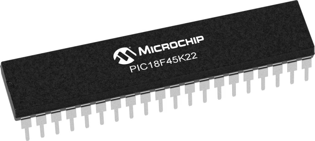
Architecture
PIC
MCU Memory (KB)
32
Silicon Vendor
Microchip
Pin count
40
RAM (Bytes)
1536
Used MCU Pins
mikroBUS™ mapper
Take a closer look
Click board™ Schematic
Step by step
Project assembly

Start by selecting your development board and Click board™. Begin with the EasyPIC v7a as your development board.


Software Support
Library Description
This library contains API for Hydrogen Click driver.
Key functions:
hydrogen_read_an_pin_value- This function reads results of AD conversion of the AN pin.hydrogen_read_an_pin_voltage- This function reads results of AD conversion of the AN pin and converts them to proportional voltage level.
Open Source
Code example
The complete application code and a ready-to-use project are available through the NECTO Studio Package Manager for direct installation in the NECTO Studio. The application code can also be found on the MIKROE GitHub account.
/*!
 * @file main.c
 * @brief Hydrogen Click Example.
 *
 * # Description
 * The demo application shows the reading of the adc
 * values given by the sensors.
 *
 * The demo application is composed of two sections :
 *
 * ## Application Init
 * Configuring Clicks and log objects.
 *
 * ## Application Task
 * Reads the adc value and prints in two forms (DEC and HEX).
 *
 * @author Jelena Milosavljevic
 *
 */

#include "board.h"
#include "log.h"
#include "hydrogen.h"

static hydrogen_t hydrogen;   /**< Hydrogen Click driver object. */
static log_t logger;    /**< Logger object. */

void application_init ( void ) {
    log_cfg_t log_cfg;  /**< Logger config object. */
    hydrogen_cfg_t hydrogen_cfg;  /**< Click config object. */

    /**
     * Logger initialization.
     * Default baud rate: 115200
     * Default log level: LOG_LEVEL_DEBUG
     * @note If USB_UART_RX and USB_UART_TX
     * are defined as HAL_PIN_NC, you will
     * need to define them manually for log to work.
     * See @b LOG_MAP_USB_UART macro definition for detailed explanation.
     */
    LOG_MAP_USB_UART( log_cfg );
    log_init( &logger, &log_cfg );
    log_info( &logger, " Application Init " );

    // Click initialization.

    hydrogen_cfg_setup( &hydrogen_cfg );
    HYDROGEN_MAP_MIKROBUS( hydrogen_cfg, MIKROBUS_1);
    if ( hydrogen_init( &hydrogen, &hydrogen_cfg ) == ADC_ERROR ) {
        log_error( &logger, " Application Init Error. " );
        log_info( &logger, " Please, run program again... " );

        for ( ; ; );
    }
    log_info( &logger, " Application Task " );
}

void application_task ( void ) {
    uint16_t hydrogen_an_value = 0;

    if ( hydrogen_read_an_pin_value ( &hydrogen, &hydrogen_an_value ) != ADC_ERROR ) {
        log_printf( &logger, " ADC Value : %u\r\n", hydrogen_an_value );
    }

    float hydrogen_an_voltage = 0;

    if ( hydrogen_read_an_pin_voltage ( &hydrogen, &hydrogen_an_voltage ) != ADC_ERROR ) {
        log_printf( &logger, " AN Voltage : %.3f[V]\r\n\n", hydrogen_an_voltage );
    }

    Delay_ms ( 1000 );
}

int main ( void )
{
    /* Do not remove this line or clock might not be set correctly. */
    #ifdef PREINIT_SUPPORTED
    preinit();
    #endif

    application_init( );

    for ( ; ; )
    {
        application_task( );
    }

    return 0;
}

// ------------------------------------------------------------------------ END
Additional Support
Resources
Category:Gas


