Achieve real-time, tailor-made pressure measurements with BM1390GLV-Z and PIC18F45K42
Reliable, accurate, and easy to use – our digital pressure sensor is the solution you've been waiting for

Published Nov 01, 2023
Click board™
Pressure 17 Click
Dev. board
EasyPIC v7
Compiler
NECTO Studio
MCU
PIC18F45K42
Discover how digital pressure sensors are revolutionizing industries with unparalleled accuracy and real-time data insights
A
A
Hardware Overview
How does it work?
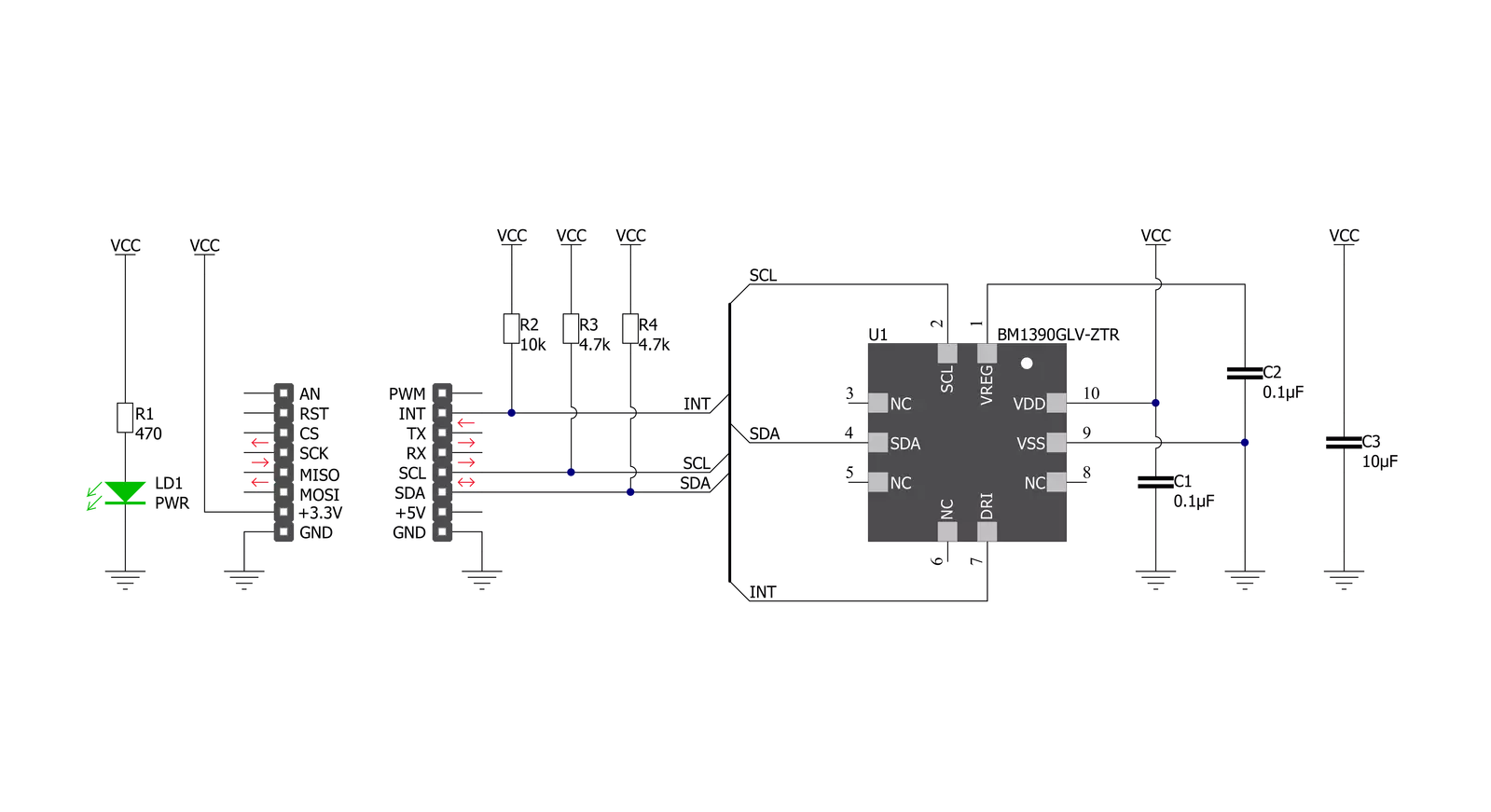
Pressure 17 Click is based on the BM1390GLV-Z, ultra-compact piezoresistive pressure sensor from Rohm Semiconductor. This MEMS-based absolute pressure sensor includes a sensing element, analog-to-digital converter, signal processing part, and digital interface that sends the digital pressure data to the host controller. The MEMS-based sensing element measures pressure from 300hPa up to 1300hPa with an accuracy of ±1hPa over a wide operating temperature range at the industry’s lowest power. It also has a built-in
temperature compensation function that internally performs temperature compensation for MEMS inside the chip, so it’s easy to get pressure information, built-in FIFO, and operation in a temperature range of -40°C to 85°C, which ensures stable operation under extreme conditions. Pressure 17 Click communicates with MCU using the standard I2C 2-Wire interface to read data and configure settings, supporting Standard Mode operation with a clock frequency of 100kHz and Fast Mode up to 400kHz. It also
possesses an additional interrupt signal, routed on the INT pin of the mikroBUS™ socket labeled as INT, indicating when a specific interrupt event occurs. This Click board™ can be operated only with a 3.3V logic voltage level. The board must perform appropriate logic voltage level conversion before using MCUs with different logic levels. Also, it comes equipped with a library containing functions and an example code that can be used as a reference for further development.


Features overview
Development board
EasyPIC v7 is the seventh generation of PIC development boards specially designed to develop embedded applications rapidly. It supports a wide range of 8-bit PIC microcontrollers from Microchip and has a broad set of unique functions, such as a powerful onboard mikroProg programmer and In-Circuit debugger over USB-B. The development board is well organized and designed so that the end-user has all the necessary elements in one place, such as switches, buttons, indicators, connectors, and others. With four different connectors for each port, EasyPIC v7 allows you to connect accessory boards, sensors, and custom electronics more efficiently than ever. Each part of
the EasyPIC v7 development board contains the components necessary for the most efficient operation of the same board. An integrated mikroProg, a fast USB 2.0 programmer with mikroICD hardware In-Circuit Debugger, offers many valuable programming/debugging options and seamless integration with the Mikroe software environment. Besides it also includes a clean and regulated power supply block for the development board. It can use various external power sources, including an external 12V power supply, 7-23V AC or 9-32V DC via DC connector/screw terminals, and a power source via the USB Type-B (USB-B) connector. Communication options such as
USB-UART and RS-232 are also included, alongside the well-established mikroBUS™ standard, three display options (7-segment, graphical, and character-based LCD), and several different DIP sockets. These sockets cover a wide range of 8-bit PIC MCUs, from PIC10F, PIC12F, PIC16F, PIC16Enh, PIC18F, PIC18FJ, and PIC18FK families. EasyPIC v7 is an integral part of the Mikroe ecosystem for rapid development. Natively supported by Mikroe software tools, it covers many aspects of prototyping and development thanks to a considerable number of different Click boards™ (over a thousand boards), the number of which is growing every day.

Microcontroller Overview
MCU Card / MCU
Architecture
PIC
MCU Memory (KB)
32
Silicon Vendor
Microchip
Pin count
40
RAM (Bytes)
2048
Used MCU Pins
mikroBUS™ mapper
Take a closer look
Click board™ Schematic
Step by step
Project assembly

Start by selecting your development board and Click board™. Begin with the EasyPIC v7 as your development board.


Software Support
Library Description
This library contains API for Pressure 17 Click driver.
Key functions:
pressure17_get_int_pin- This function returns the INT pin logic statepressure17_read_data- This function checks if the data is ready and then reads the pressure and temperature raw data and converts them to millibar and Celsius respectfullypressure17_write_register- This function writes a data byte to the selected register by using I2C serial interface
Open Source
Code example
The complete application code and a ready-to-use project are available through the NECTO Studio Package Manager for direct installation in the NECTO Studio. The application code can also be found on the MIKROE GitHub account.
/*!
 * @file main.c
 * @brief Pressure17 Click example
 *
 * # Description
 * This example demonstrates the use of Pressure 17 Click board by reading and displaying
 * the pressure and temperature data.
 *
 * The demo application is composed of two sections :
 *
 * ## Application Init
 * Initializes the driver and performs the Click default configuration.
 *
 * ## Application Task
 * Waits for the data ready interrupt and then reads the pressure [mbar] and temperature [C] data
 * and displays the results on the USB UART approximately every 200ms.
 *
 * @author Stefan Filipovic
 *
 */

#include "board.h"
#include "log.h"
#include "pressure17.h"

static pressure17_t pressure17;
static log_t logger;

void application_init ( void )
{
    log_cfg_t log_cfg;  /**< Logger config object. */
    pressure17_cfg_t pressure17_cfg;  /**< Click config object. */

    /**
     * Logger initialization.
     * Default baud rate: 115200
     * Default log level: LOG_LEVEL_DEBUG
     * @note If USB_UART_RX and USB_UART_TX
     * are defined as HAL_PIN_NC, you will
     * need to define them manually for log to work.
     * See @b LOG_MAP_USB_UART macro definition for detailed explanation.
     */
    LOG_MAP_USB_UART( log_cfg );
    log_init( &logger, &log_cfg );
    log_info( &logger, " Application Init " );

    // Click initialization.
    pressure17_cfg_setup( &pressure17_cfg );
    PRESSURE17_MAP_MIKROBUS( pressure17_cfg, MIKROBUS_1 );
    if ( I2C_MASTER_ERROR == pressure17_init( &pressure17, &pressure17_cfg ) )
    {
        log_error( &logger, " Communication init." );
        for ( ; ; );
    }

    if ( PRESSURE17_ERROR == pressure17_default_cfg ( &pressure17 ) )
    {
        log_error( &logger, " Default configuration." );
        for ( ; ; );
    }

    log_info( &logger, " Application Task " );
}

void application_task ( void )
{
    if ( !pressure17_get_int_pin ( &pressure17 ) )
    {
        float pressure, temperature;
        if ( PRESSURE17_OK == pressure17_read_data ( &pressure17, &pressure, &temperature ) )
        {
            log_printf ( &logger, " Pressure: %.2f mbar\r\n Temperature: %.2f C\r\n\n", pressure, temperature );
        }
    }
}

int main ( void )
{
    /* Do not remove this line or clock might not be set correctly. */
    #ifdef PREINIT_SUPPORTED
    preinit();
    #endif

    application_init( );

    for ( ; ; )
    {
        application_task( );
    }

    return 0;
}

// ------------------------------------------------------------------------ END


