Synchronize and secure your SPI data flow effortlessly with DCL541A01 and PIC18F4610
Isolate to elevate: Transforming SPI communication with precision and power!
Published Nov 15, 2023
Click board™
SPI Isolator 5 Click
Dev. board
EasyPIC v7
Compiler
NECTO Studio
MCU
PIC18F4610
Our SPI isolator ensures data integrity by providing a robust barrier against electrical noise, guaranteeing a seamless and secure serial interface.
A
A
Hardware Overview
How does it work?
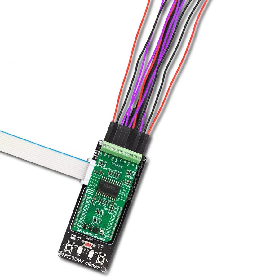
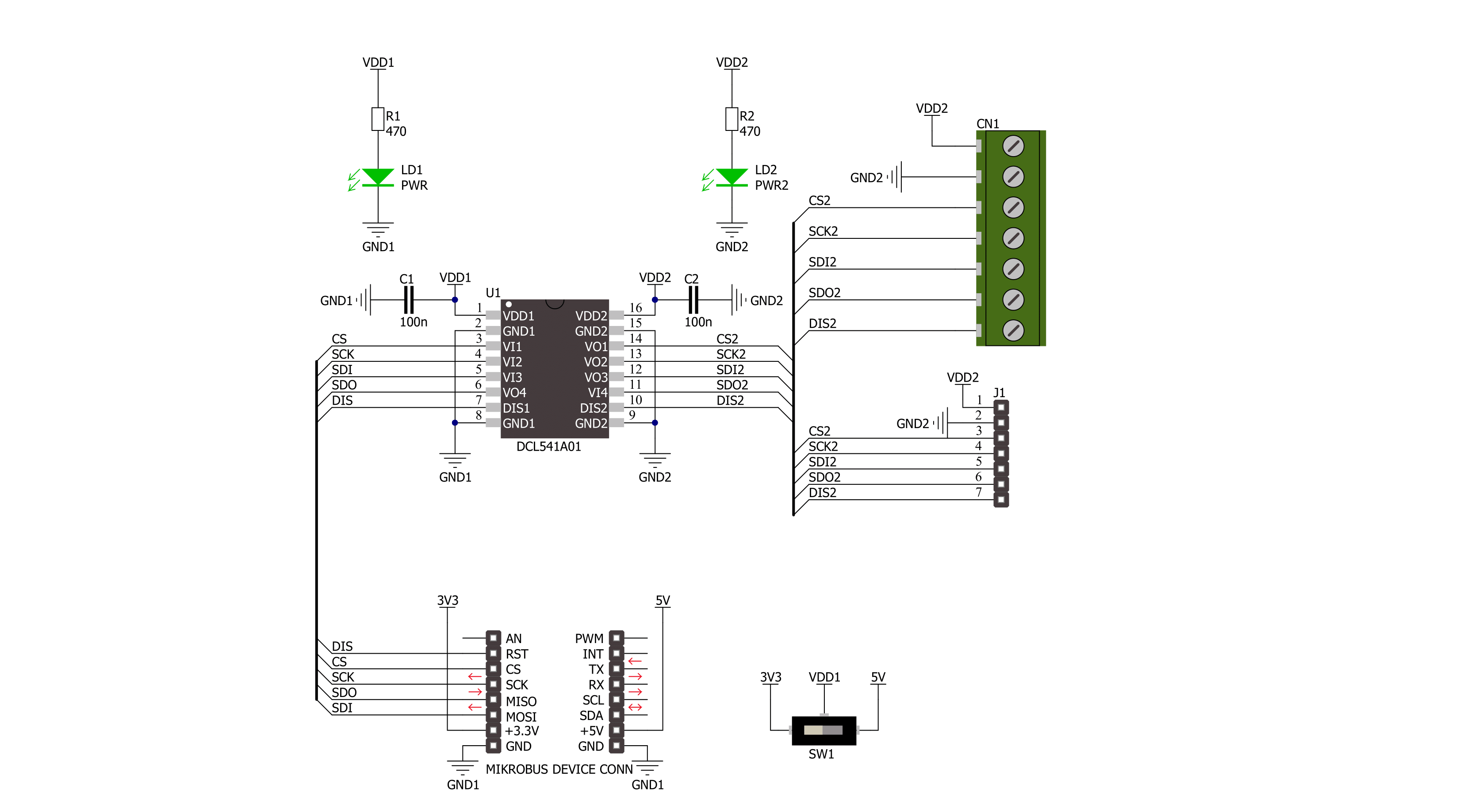
SPI Isolator 5 Click is based on the DCL541A01, a high-speed quad-channel digital isolator from Toshiba Semiconductor. The DCL541A01 stands out with its exceptional performance capabilities, made possible by leveraging Toshiba's advanced CMOS technology and a magnetic coupling structure. Not only does it meet the stringent safety standards of UL 1577 certification, but it also boasts an impressive withstand voltage rating of 5kVrms. Furthermore, its operating range spans from 2.25V to 5.5V, enabling seamless integration with lower voltage systems and facilitating voltage translation functionality across isolation barriers. With its versatility, this Click board™ is well-suited
for various applications, including industrial automation systems, motor control, inverters, and more. SPI Isolator 5 Click communicates with an MCU using the SPI serial interface with a maximum data rate of 150Mbps. The isolated lines are divided into two groups with the same lines. The first group comes in the form of 5 screw terminals, while the second forms a classic male 5-header row for easier jumper wire usage. Both groups of connectors have the same functions. You can distinguish the power VDD2 and GND2 lines from the data lines, which are CS2, SCK2, SDI2, SDO2, and DIS2. The DIS and DIS2 pins have the same function: to disable the lines from the
side of the isolator on which they are located. By setting the DIS pin to a high logic level, the input signals are disabled, and by setting it to a low logic level, they are enabled. The isolator can work with external supply voltages from 2.25V up to 5.5V, and the existence of an external power supply is easily visible using the PWR2 LED indicator. This Click board™ can operate with either 3.3V or 5V logic voltage levels selected via the VCC SEL switch. This way, both 3.3V and 5V capable MCUs can use the communication lines properly. Also, it comes equipped with a library containing functions and an example code that can be used as a reference for further development.

Features overview
Development board
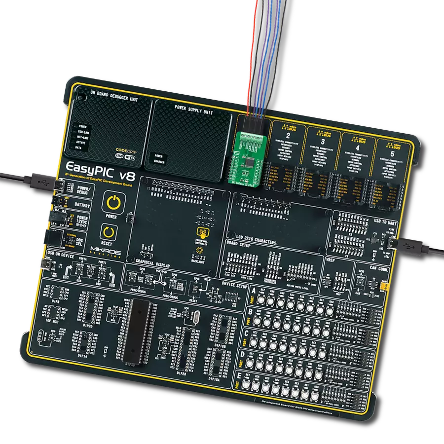
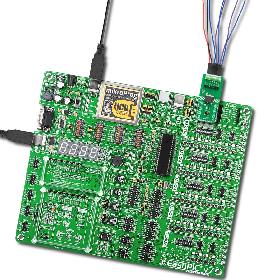
EasyPIC v7 is the seventh generation of PIC development boards specially designed to develop embedded applications rapidly. It supports a wide range of 8-bit PIC microcontrollers from Microchip and has a broad set of unique functions, such as a powerful onboard mikroProg programmer and In-Circuit debugger over USB-B. The development board is well organized and designed so that the end-user has all the necessary elements in one place, such as switches, buttons, indicators, connectors, and others. With four different connectors for each port, EasyPIC v7 allows you to connect accessory boards, sensors, and custom electronics more efficiently than ever. Each part of
the EasyPIC v7 development board contains the components necessary for the most efficient operation of the same board. An integrated mikroProg, a fast USB 2.0 programmer with mikroICD hardware In-Circuit Debugger, offers many valuable programming/debugging options and seamless integration with the Mikroe software environment. Besides it also includes a clean and regulated power supply block for the development board. It can use various external power sources, including an external 12V power supply, 7-23V AC or 9-32V DC via DC connector/screw terminals, and a power source via the USB Type-B (USB-B) connector. Communication options such as
USB-UART and RS-232 are also included, alongside the well-established mikroBUS™ standard, three display options (7-segment, graphical, and character-based LCD), and several different DIP sockets. These sockets cover a wide range of 8-bit PIC MCUs, from PIC10F, PIC12F, PIC16F, PIC16Enh, PIC18F, PIC18FJ, and PIC18FK families. EasyPIC v7 is an integral part of the Mikroe ecosystem for rapid development. Natively supported by Mikroe software tools, it covers many aspects of prototyping and development thanks to a considerable number of different Click boards™ (over a thousand boards), the number of which is growing every day.

Microcontroller Overview
MCU Card / MCU
Architecture
PIC
MCU Memory (KB)
64
Silicon Vendor
Microchip
Pin count
40
RAM (Bytes)
3968
Used MCU Pins
mikroBUS™ mapper
Take a closer look
Click board™ Schematic
Step by step
Project assembly

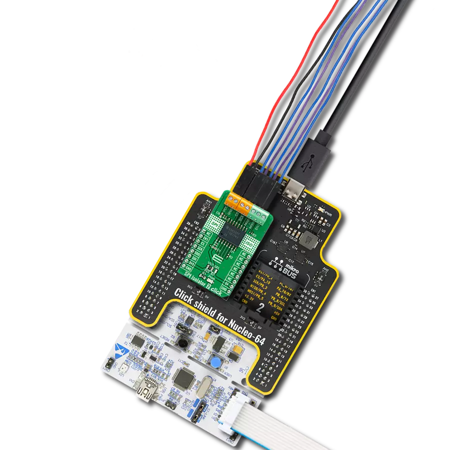
Start by selecting your development board and Click board™. Begin with the EasyPIC v7 as your development board.


Software Support
Library Description
This library contains API for SPI Isolator 5 Click driver.
Key functions:
spiisolator5_write- SPI Isolator 5 data writing function.spiisolator5_read- SPI Isolator 5 data reading function.spiisolator5_transfer- SPI Isolator 5 transfer function.
Open Source
Code example
The complete application code and a ready-to-use project are available through the NECTO Studio Package Manager for direct installation in the NECTO Studio. The application code can also be found on the MIKROE GitHub account.
/*!
 * @file main.c
 * @brief SPI Isolator 5 Click example
 *
 * # Description
 * This example demonstrates the use of SPI Isolator 5 Click board
 * by reading the manufacturer ID and device ID
 * of the connected Flash 11 Click board.
 *
 * The demo application is composed of two sections :
 *
 * ## Application Init
 * The initialization of SPI module, log UART, and additional pins.
 * After the driver init, the app performs enabling a device.
 *
 * ## Application Task
 * The demo application reads and checks the manufacturer ID and
 * device ID of the connected Flash 11 Click board.
 * Results are being sent to the UART Terminal, where you can track their changes.
 *
 * @author Nenad Filipovic
 *
 */

#include "board.h"
#include "log.h"
#include "spiisolator5.h"

#define FLASH11_CMD_GET_ID         0x90, 0x00, 0x00, 0x00, 0x00, 0x00
#define FLASH11_MANUFACTURER_ID    0x1F
#define FLASH11_DEVICE_ID          0x15

static spiisolator5_t spiisolator5;
static log_t logger;

void application_init ( void )
{
    log_cfg_t log_cfg;  /**< Logger config object. */
    spiisolator5_cfg_t spiisolator5_cfg;  /**< Click config object. */

    /**
     * Logger initialization.
     * Default baud rate: 115200
     * Default log level: LOG_LEVEL_DEBUG
     * @note If USB_UART_RX and USB_UART_TX
     * are defined as HAL_PIN_NC, you will
     * need to define them manually for log to work.
     * See @b LOG_MAP_USB_UART macro definition for detailed explanation.
     */
    LOG_MAP_USB_UART( log_cfg );
    log_init( &logger, &log_cfg );
    log_info( &logger, " Application Init " );

    // Click initialization.
    spiisolator5_cfg_setup( &spiisolator5_cfg );
    SPIISOLATOR5_MAP_MIKROBUS( spiisolator5_cfg, MIKROBUS_1 );
    if ( SPI_MASTER_ERROR == spiisolator5_init( &spiisolator5, &spiisolator5_cfg ) )
    {
        log_error( &logger, " Communication init." );
        for ( ; ; );
    }

    spiisolator5_enable( &spiisolator5 );
    Delay_ms ( 100 );

    log_info( &logger, " Application Task " );
    log_printf( &logger, " -----------------------\r\n" );
    Delay_ms ( 100 );
}

void application_task ( void )
{
    static uint8_t cmd_get_id[ 6 ] = { FLASH11_CMD_GET_ID };
    static uint8_t read_id[ 6 ] = { 0 };
    if ( SPIISOLATOR5_OK == spiisolator5_transfer( &spiisolator5, &cmd_get_id[ 0 ], &read_id[ 0 ], 6 ) )
    {
        if ( ( FLASH11_MANUFACTURER_ID == read_id[ 4 ] ) && ( FLASH11_DEVICE_ID == read_id[ 5 ] ) )
        {
            log_printf( &logger, " Manufacturer ID: 0x%.2X\r\n", ( uint16_t ) read_id[ 4 ] );
            log_printf( &logger, " Device ID: 0x%.2X    \r\n", ( uint16_t ) read_id[ 5 ] );
            log_printf( &logger, " -----------------------\r\n" );
            Delay_ms ( 1000 );
            Delay_ms ( 1000 );
            Delay_ms ( 1000 );
        }
    }
}

int main ( void )
{
    /* Do not remove this line or clock might not be set correctly. */
    #ifdef PREINIT_SUPPORTED
    preinit();
    #endif

    application_init( );

    for ( ; ; )
    {
        application_task( );
    }

    return 0;
}

// ------------------------------------------------------------------------ END