Handle demanding power requirements easily with MIC45404 and PIC18LF46K22
Bucktastic performance!
Published Jul 30, 2023
Click board™
Buck 2 Click
Dev. board
EasyPIC v7
Compiler
NECTO Studio
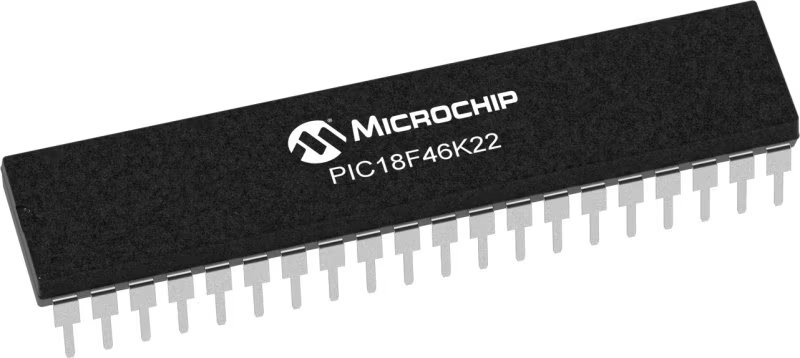
MCU
PIC18LF46K22
Embrace the future of power efficiency with our high-efficiency buck regulator that streamlines voltage conversion and sets new standards for sustainable electronics
A
A
Hardware Overview
How does it work?
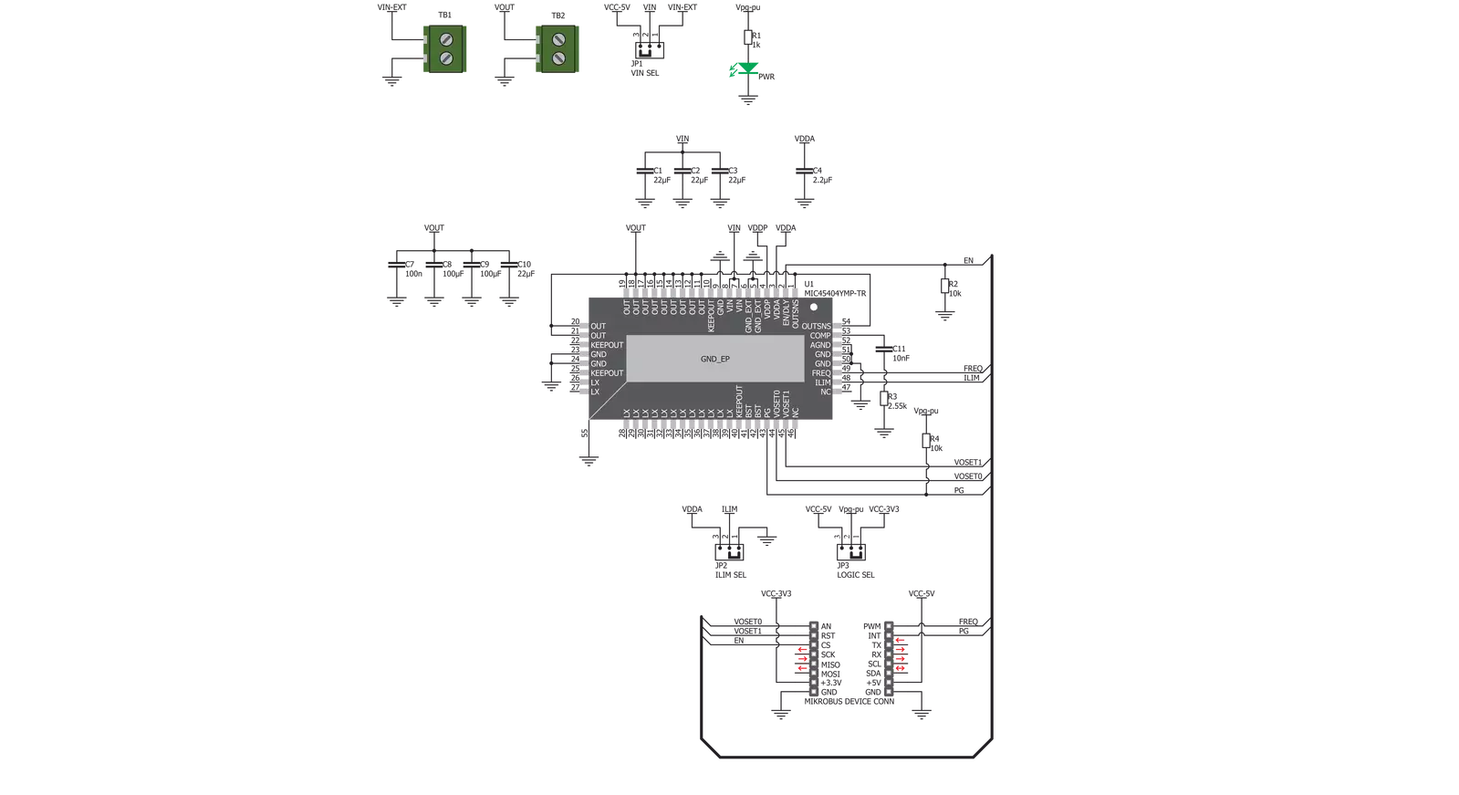
Buck 2 Click is based on the MIC45404, a 19V 5A ultra-low profile DC-to-DC power module by Microchip. This IC is a valley current mode controlled power module, meaning it has a faster response than the traditional peak current mode control, thus a better response to transients. This IC requires minimal external components, making the whole device robust and easy to work with. Unlike traditional switching regulators, this one does not require external feedback components - it is enough to connect the OUTSNS pin to the output voltage directly. This allows for more accurate control over the voltage regulation. Buck 2 click allows configuring certain working parameters, such as the output voltage, current limit threshold, and PWM switching frequency, by changing the states of the dedicated pins. Those pins are routed to the mikroBUS™ socket or equipped with the SMD jumpers so the end user can set them. These pins can be set to the GND, VCC, or left afloat - high impedance mode (HIGH-Z). They are sampled when the internal voltage is stabilized, and their state is latched - further changes will not affect the selected configuration. The output voltage level is selected by the VOSET0 and VOSET1 pins of the MIC45404 IC, routed to the
mikroBUS™ AN and RST pins, respectively. This gives a total of nine possible voltage level combinations. The FREQ pin can change the PWM switching frequency, routed to the PWM pin of the mikroBUS™ socket. The switching frequency is related to the selected output voltage. For this reason, it is routed to the mikroBUS™ socket so that the voltage output and the corresponding frequency for the selected voltage can be set. There are three possible frequency values: 400kHz, 565kHz, and 790kHz. The onboard SMD jumper selects the current limiting, labeled as ILIM SEL. Limiting the current to 3A, 4A, and 5A is possible. The current limiting is instantaneous, and the MIC45404 IC offers current limit and current sensing on both high-side and low-side internal MOSFET switches. It also features a special Hiccup mode, which reduces power dissipation in prolonged overload or short circuit situations. The internal counter is incremented when a low-end MOSFET current limiting event occurs. A PWM cycle with no low-end MOSFET limiting events will decrease the internal counter. If the internal counter reaches 0Fh, both MOSFETs will be tri-stated, and the power to the output will be cut off. After a predetermined wait time has expired,
the MIC45404 IC will be restarted and attempt a new soft-startup sequence. This mechanism ensures that no false overload events are generated. The EN/DLY pin is used to enable the device. A HIGH logic level on this pin will start up the internal sections of the MIC45404 IC. This pin is routed to the mikroBUS™ CS pin, and since it is in an open drain configuration, it is pulled by the resistor to the GND. The PG pin indicates the power good condition of the output. When the voltage on the output (OUTSNS) drops under 90% of the regulated voltage, this pin is set to a LOW logic level, indicating irregular output voltage. An onboard pull-up resistor pulls This pin to a HIGH logic level since it is configured as the open drain output. It is routed to the mikroBUS™ INT pin. Buck 2 click is equipped with two screw terminals to connect the input voltage source and the output load. The input voltage source is selectable between the +5V rail from the mikroBUS™ and the voltage at the input terminal. It also has an onboard LOGIC SEL SMD jumper, used to set up the logic voltage level so that both 3.3V and 5V capable MCUs can be used.

Features overview
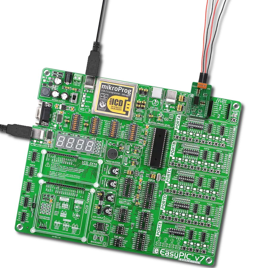
Development board
EasyPIC v7 is the seventh generation of PIC development boards specially designed to develop embedded applications rapidly. It supports a wide range of 8-bit PIC microcontrollers from Microchip and has a broad set of unique functions, such as a powerful onboard mikroProg programmer and In-Circuit debugger over USB-B. The development board is well organized and designed so that the end-user has all the necessary elements in one place, such as switches, buttons, indicators, connectors, and others. With four different connectors for each port, EasyPIC v7 allows you to connect accessory boards, sensors, and custom electronics more efficiently than ever. Each part of
the EasyPIC v7 development board contains the components necessary for the most efficient operation of the same board. An integrated mikroProg, a fast USB 2.0 programmer with mikroICD hardware In-Circuit Debugger, offers many valuable programming/debugging options and seamless integration with the Mikroe software environment. Besides it also includes a clean and regulated power supply block for the development board. It can use various external power sources, including an external 12V power supply, 7-23V AC or 9-32V DC via DC connector/screw terminals, and a power source via the USB Type-B (USB-B) connector. Communication options such as
USB-UART and RS-232 are also included, alongside the well-established mikroBUS™ standard, three display options (7-segment, graphical, and character-based LCD), and several different DIP sockets. These sockets cover a wide range of 8-bit PIC MCUs, from PIC10F, PIC12F, PIC16F, PIC16Enh, PIC18F, PIC18FJ, and PIC18FK families. EasyPIC v7 is an integral part of the Mikroe ecosystem for rapid development. Natively supported by Mikroe software tools, it covers many aspects of prototyping and development thanks to a considerable number of different Click boards™ (over a thousand boards), the number of which is growing every day.

Microcontroller Overview
MCU Card / MCU
Architecture
PIC
MCU Memory (KB)
64
Silicon Vendor
Microchip
Pin count
40
RAM (Bytes)
3896
Used MCU Pins
mikroBUS™ mapper
Take a closer look
Click board™ Schematic
Step by step
Project assembly

Start by selecting your development board and Click board™. Begin with the EasyPIC v7 as your development board.


Track your results in real time
Application Output
1. Application Output - In Debug mode, the 'Application Output' window enables real-time data monitoring, offering direct insight into execution results. Ensure proper data display by configuring the environment correctly using the provided tutorial.

2. UART Terminal - Use the UART Terminal to monitor data transmission via a USB to UART converter, allowing direct communication between the Click board™ and your development system. Configure the baud rate and other serial settings according to your project's requirements to ensure proper functionality. For step-by-step setup instructions, refer to the provided tutorial.

3. Plot Output - The Plot feature offers a powerful way to visualize real-time sensor data, enabling trend analysis, debugging, and comparison of multiple data points. To set it up correctly, follow the provided tutorial, which includes a step-by-step example of using the Plot feature to display Click board™ readings. To use the Plot feature in your code, use the function: plot(*insert_graph_name*, variable_name);. This is a general format, and it is up to the user to replace 'insert_graph_name' with the actual graph name and 'variable_name' with the parameter to be displayed.

Software Support
Library Description
This library contains API for Buck 2 Click driver.
Key functions:
buck2_set_output_voltage- Function settings output voltagebuck2_get_power_good- Function reads state PG pinbuck2_set_power_mode- Function settings chip mode
Open Source
Code example
The complete application code and a ready-to-use project are available through the NECTO Studio Package Manager for direct installation in the NECTO Studio. The application code can also be found on the MIKROE GitHub account.
/*!
 * \file
 * \brief Buck 2 Click example
 *
 * # Description
 * This application demonstrates the use of Buck 2 Click board.
 *
 * The demo application is composed of two sections :
 *
 * ## Application Init
 * Initializes the driver and configures the Click board.
 *
 * ## Application Task
 * Sets a different output voltage every 5 seconds then checks if the voltage on
 * the output (OUTSNS) drops under 90% of the regulated voltage
 * and displays an appropriate message on USB UART.
 *
 * \author Katarina Perendic
 *
 */
// ------------------------------------------------------------------- INCLUDES

#include "board.h"
#include "log.h"
#include "buck2.h"

// ------------------------------------------------------------------ VARIABLES

static buck2_t buck2;
static log_t logger;

// ------------------------------------------------------ APPLICATION FUNCTIONS

void application_init ( void )
{
    log_cfg_t log_cfg;
    buck2_cfg_t cfg;

    /**
     * Logger initialization.
     * Default baud rate: 115200
     * Default log level: LOG_LEVEL_DEBUG
     * @note If USB_UART_RX and USB_UART_TX
     * are defined as HAL_PIN_NC, you will
     * need to define them manually for log to work.
     * See @b LOG_MAP_USB_UART macro definition for detailed explanation.
     */
    LOG_MAP_USB_UART( log_cfg );
    log_init( &logger, &log_cfg );
    log_info( &logger, "---- Application Init ----" );

    //  Click initialization.

    buck2_cfg_setup( &cfg );
    BUCK2_MAP_MIKROBUS( cfg, MIKROBUS_1 );
    buck2_init( &buck2, &cfg );

    buck2_default_cfg( &buck2 );
}

void application_task ( void )
{
    uint8_t pg_state;

    buck2_set_output_voltage( &buck2, BUCK2_SET_VOLTAGE_3300mV );
    log_printf( &logger, "---- Output voltage is 3300 mV ----\r\n" );
    Delay_ms ( 1000 );
    Delay_ms ( 1000 );
    Delay_ms ( 1000 );
    Delay_ms ( 1000 );
    Delay_ms ( 1000 );
    pg_state = buck2_get_power_good( &buck2 );
    if ( pg_state == 0 )
    {
        log_info( &logger, "---- Voltage of the output dropped under 90%% of the regulated voltage ----" );
    }
    buck2_set_output_voltage( &buck2, BUCK2_SET_VOLTAGE_2500mV );
    log_printf( &logger, "---- Output voltage is 2500 mV ----\r\n" );
    Delay_ms ( 1000 );
    Delay_ms ( 1000 );
    Delay_ms ( 1000 );
    Delay_ms ( 1000 );
    Delay_ms ( 1000 );
    pg_state = buck2_get_power_good( &buck2 );
    if ( pg_state == 0 )
    {
        log_info( &logger, "---- Voltage of the output dropped under 90%% of the regulated voltage ----" );
    }
    buck2_set_output_voltage( &buck2, BUCK2_SET_VOLTAGE_1800mV );
    log_printf( &logger, "---- Output voltage is 1800 mV ----\r\n" );
    Delay_ms ( 1000 );
    Delay_ms ( 1000 );
    Delay_ms ( 1000 );
    Delay_ms ( 1000 );
    Delay_ms ( 1000 );
    pg_state = buck2_get_power_good( &buck2 );
    if ( pg_state == 0 )
    {
        log_info( &logger, "---- Voltage of the output dropped under 90%% of the regulated voltage ----" );
    }
    buck2_set_output_voltage( &buck2, BUCK2_SET_VOLTAGE_1500mV );
    log_printf( &logger, "---- Output voltage is 1500 mV ----\r\n" );
    log_printf( &logger, "-----------------------------------\r\n" );
    Delay_ms ( 1000 );
    Delay_ms ( 1000 );
    Delay_ms ( 1000 );
    Delay_ms ( 1000 );
    Delay_ms ( 1000 );
    pg_state = buck2_get_power_good( &buck2 );
    if ( pg_state == 0 )
    {
        log_info( &logger, "---- Voltage of the output dropped under 90%% of the regulated voltage ----" );
    }
}

int main ( void )
{
    /* Do not remove this line or clock might not be set correctly. */
    #ifdef PREINIT_SUPPORTED
    preinit();
    #endif

    application_init( );

    for ( ; ; )
    {
        application_task( );
    }

    return 0;
}

// ------------------------------------------------------------------------ END


