Create various RGB light animations and patterns with NCP5623B and dsPIC30F4011
Unleash the spectrum!

Published Sep 05, 2023
Click board™
Led Driver 3 Click
Dev. board
EasyPIC v7 for dsPIC30
Compiler
NECTO Studio
MCU
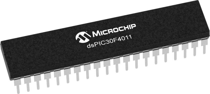
dsPIC30F4011
Enhance user experiences in your products with our RGB driver, allowing for customized color schemes and mood-enhancing lighting
A
A
Hardware Overview
How does it work?
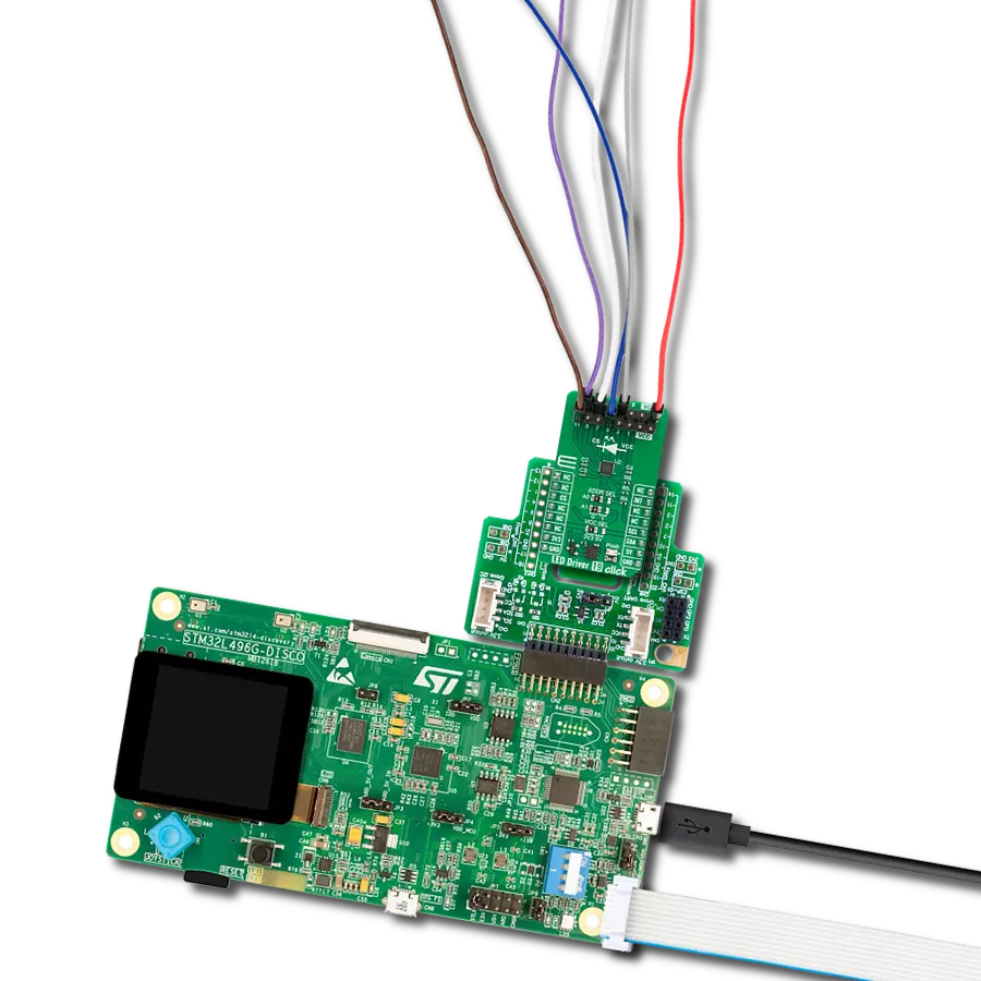
LED Driver 3 Click is based on the NCP5623B, a triple output RGB LED driver controlled through the I2C protocol from ON Semiconductors. This IC has an internal DC/DC converter that works as a high-efficiency charge pump, providing the required DC voltage for all three LED segments. The current flow through each LED segment is regulated by an internal current mirror associated with each channel. The gradual dimming function allows an easy way of dimming RGB LED intensity. With a simple I2C command, it is possible to trigger either upward or downward dimming. Dimming will affect the current through the LED segments, but the internal current limiter does not exceed the maximum allowed current set by the onboard resistor. The integrated PWM operates with five bits, having 32 steps to cover the associated LED channel's full modulation (0 to 100%). A value of 0x00h will turn the associated
LED completely OFF, while 0x1Fh will set the LED to a programmed LED current value. The last three bits (MSB) are used to set the desired command register: PWM1, PWM2, PWM3, dimming direction, gradual dimming, LED current, and more. It should be noted that the gradual dimming function affects the illumination by changing the LED current intensity, while PWM affects the associated LED illumination by changing the pulse width - e.g., it is possible to set the desired color by setting the PWM modulation of each color component, and then gradually dim the brightness of the final color mix up or down by the gradual dimming option - affecting the current through all the LED segments simultaneously. It is also possible to set the fixed value for the current through the LED segments via the I2C interface when gradual dimming is not needed. To allow operation on both 3.3V and 5V MCUs, LED Driver 3
Click employs PCA9306, a dual bidirectional I2C/SMBUS voltage level translator from Texas Instruments. This IC allows the click board to be interfaced with 3.3V and 5V MCUs. The logic voltage level shifting is done automatically, so no SMD jumpers are needed in this case. Both 3.3V and 5V rails are needed for this circuit to be operational. The click board is also equipped with an RGB LED. This is a high-brightness RGB LED with a wide viewing angle that can get very hot and bright while operated with maximum current. For this reason, care must be taken not to touch it or watch directly at the LED. SCL1 and SDA1 lines from the I2C level shifter are routed to the standard mikroBUS™ I2C pins, labeled as SCL and SDA. The click board™ already contains pull-up resistors, so no additional parts are needed to work with the click board.


Features overview
Development board
EasyPIC v7 for dsPIC30 is the seventh generation of PIC development boards specially designed to develop embedded applications rapidly. It supports a wide range of 16-bit PIC microcontrollers from Microchip and has a broad set of unique functions, such as a powerful onboard mikroProg programmer and In-Circuit debugger over USB. The development board is well organized and designed so that the end-user has all the necessary elements in one place, such as switches, buttons, indicators, connectors, and others. With three different connectors for each port, EasyPIC v7 for dsPIC30 allows you to connect accessory boards, sensors, and custom electronics more efficiently
than ever. Each part of the EasyPIC v7 for dsPIC30 development board contains the components necessary for the most efficient operation of the same board. An integrated mikroProg, a fast USB 2.0 programmer with mikroICD hardware In-Circuit Debugger, offers many valuable programming/debugging options and seamless integration with the Mikroe software environment. Besides it also includes a clean and regulated power supply block for the development board. It can use various external power sources, including an external 12V power supply, 7-23V AC or 9-32V DC via DC connector/screw terminals, and a power source via the USB Type-B (USB-B) connector.
Communication options such as USB-UART, RS-232, and CAN are included, alongside the well-established mikroBUS™ standard, three display options (7-segment, graphical, and character-based LCD), and several different DIP sockets which cover a wide range of 16-bit dsPIC/PIC24 MCUs. EasyPIC v7 for dsPIC30 is an integral part of the Mikroe ecosystem for rapid development. Natively supported by Mikroe software tools, it covers many aspects of prototyping and development thanks to a considerable number of different Click boards™ (over a thousand boards), the number of which is growing every day.

Microcontroller Overview
MCU Card / MCU
Architecture
dsPIC
MCU Memory (KB)
48
Silicon Vendor
Microchip
Pin count
40
RAM (Bytes)
2048
Used MCU Pins
mikroBUS™ mapper
Take a closer look
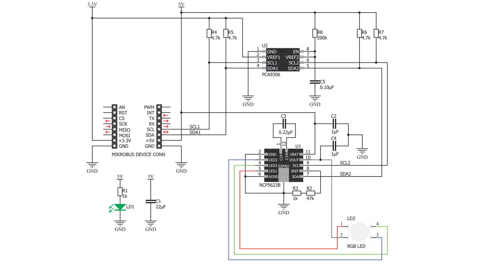
Click board™ Schematic
Step by step
Project assembly

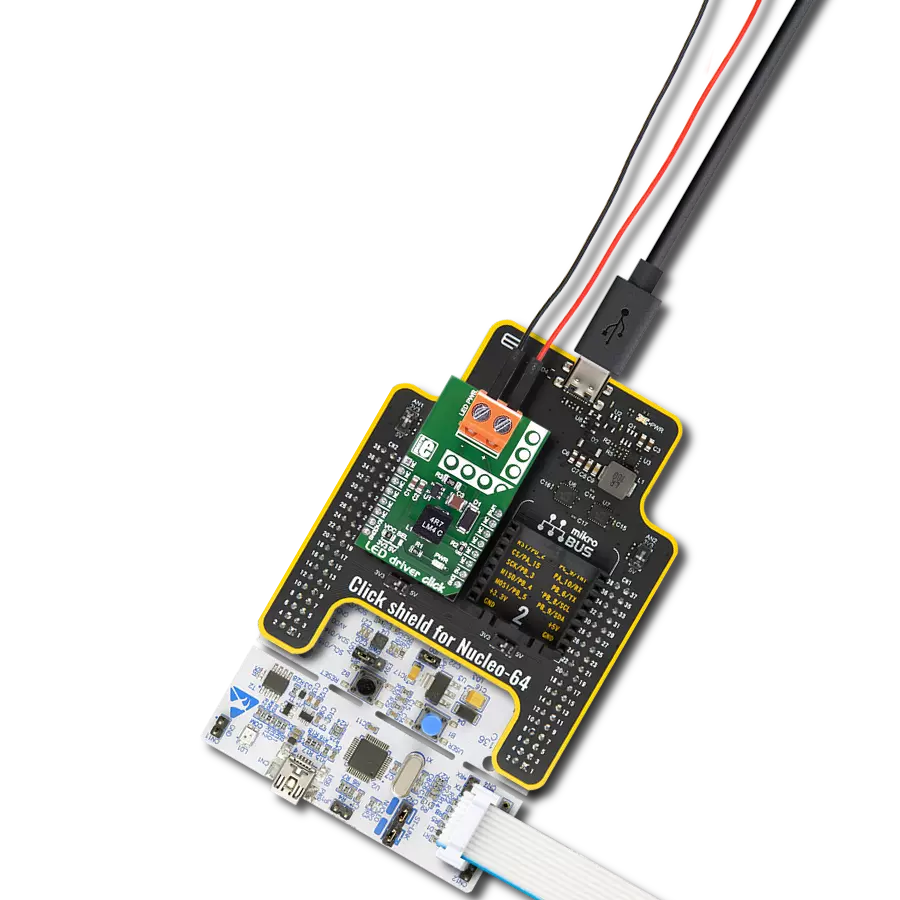
Start by selecting your development board and Click board™. Begin with the EasyPIC v7 for dsPIC30 as your development board.


Track your results in real time
Application Output
1. Application Output - In Debug mode, the 'Application Output' window enables real-time data monitoring, offering direct insight into execution results. Ensure proper data display by configuring the environment correctly using the provided tutorial.

2. UART Terminal - Use the UART Terminal to monitor data transmission via a USB to UART converter, allowing direct communication between the Click board™ and your development system. Configure the baud rate and other serial settings according to your project's requirements to ensure proper functionality. For step-by-step setup instructions, refer to the provided tutorial.

3. Plot Output - The Plot feature offers a powerful way to visualize real-time sensor data, enabling trend analysis, debugging, and comparison of multiple data points. To set it up correctly, follow the provided tutorial, which includes a step-by-step example of using the Plot feature to display Click board™ readings. To use the Plot feature in your code, use the function: plot(*insert_graph_name*, variable_name);. This is a general format, and it is up to the user to replace 'insert_graph_name' with the actual graph name and 'variable_name' with the parameter to be displayed.

Software Support
Library Description
This library contains API for LED Driver 3 Click driver.
Key functions:
leddriver3_set_rgb_color- This function sets the color of the rgb LEDs through the parameters for red, green and blueleddriver3_set_color- This function sets colorleddriver3_set_timer- This function sets timer for increase or decrease light
Open Source
Code example
The complete application code and a ready-to-use project are available through the NECTO Studio Package Manager for direct installation in the NECTO Studio. The application code can also be found on the MIKROE GitHub account.
/*!
 * \file
 * \brief LedDriver3 Click example
 *
 * # Description
 * This app changes color and intensity of light.
 *
 * The demo application is composed of two sections :
 *
 * ## Application Init
 * Driver initialize.
 *
 * ## Application Task
 * Changes color and intensity of light.
 *
 * \author MikroE Team
 *
 */
// ------------------------------------------------------------------- INCLUDES

#include "board.h"
#include "log.h"
#include "leddriver3.h"

// ------------------------------------------------------------------ VARIABLES

static leddriver3_t leddriver3;
static log_t logger;
static leddriver3_rgb_t rgb;

// ------------------------------------------------------ APPLICATION FUNCTIONS

void application_init ( void )
{
    log_cfg_t log_cfg;
    leddriver3_cfg_t cfg;

    /**
     * Logger initialization.
     * Default baud rate: 115200
     * Default log level: LOG_LEVEL_DEBUG
     * @note If USB_UART_RX and USB_UART_TX
     * are defined as HAL_PIN_NC, you will
     * need to define them manually for log to work.
     * See @b LOG_MAP_USB_UART macro definition for detailed explanation.
     */
    LOG_MAP_USB_UART( log_cfg );
    log_init( &logger, &log_cfg );
    log_info( &logger, "---- Application Init ----\r\n" );

    //  Click initialization.

    leddriver3_cfg_setup( &cfg );
    LEDDRIVER3_MAP_MIKROBUS( cfg, MIKROBUS_1 );

    if ( LEDDRIVER3_INIT_ERROR == leddriver3_init( &leddriver3, &cfg ) )
    {
        log_info( &logger, "---- Init Error ----\r\n" );
        log_info( &logger, "---- Run program again ----\r\n" );

        for ( ; ; );
    }

    log_info( &logger, "---- Init Done ----\r\n" );
}

void application_task ( void )
{
    rgb.red = 0x40;
    rgb.green = 0x7F;
    rgb.blue = 0x80;

    leddriver3_set_intensity( &leddriver3, LEDDRIVER3_INCREMENT | LEDDRIVER3_INTENSITY_8 );
    leddriver3_set_timer( &leddriver3, LEDDRIVER3_TIMER_8ms | LEDDRIVER3_TIMER_16ms );
    leddriver3_set_color( &leddriver3, LEDDRIVER3_COLOR_RED );
    Delay_ms ( 1000 );

    leddriver3_set_intensity( &leddriver3, LEDDRIVER3_CONSTANT | LEDDRIVER3_INTENSITY_16 );
    leddriver3_set_color( &leddriver3, LEDDRIVER3_COLOR_PURPLE );
    Delay_ms ( 1000 );
    leddriver3_set_color( &leddriver3, LEDDRIVER3_COLOR_BLUE );
    Delay_ms ( 1000 );

    leddriver3_set_rgb_color( &leddriver3, &rgb );
    Delay_ms ( 1000 );
}

int main ( void )
{
    /* Do not remove this line or clock might not be set correctly. */
    #ifdef PREINIT_SUPPORTED
    preinit();
    #endif

    application_init( );

    for ( ; ; )
    {
        application_task( );
    }

    return 0;
}

// ------------------------------------------------------------------------ END
Additional Support
Resources
Category:LED Drivers