Achieve precise resistance adjustments with AD5235 and ATmega32
Ditch the traditional, embrace the digital

Published Nov 01, 2023
Click board™
DIGI POT 9 Click
Dev. board
EasyAVR v7
Compiler
NECTO Studio
MCU
ATmega32
By providing programmable resistance settings, our digital potentiometers find application in scenarios requiring remote adjustments, eliminating the need for manual intervention
A
A
Hardware Overview
How does it work?
DIGI POT 9 Click is based on the AD5235, a digital potentiometer that operates as a proper variable resistor from Analog Devices. The resistor wiper position is determined by the RDAC register contents, that act as a scratchpad register, allowing unlimited changes of resistance settings. The scratchpad register can be programmed with any position setting using the standard SPI serial interface by loading the 24-bit data word. The nominal resistance of the RDAC between terminal A and terminal B (RAB) is 250kΩ with 1024 positions (10-bit resolution). This Click board™ communicates with MCU through a standard SPI interface and operates at clock rates up to 10MHz, supporting the two most common SPI modes, SPI Mode 0 and 3. In the data word format, the first four bits are commands, the following four bits are addresses, and the last 16 bits are data. When a
specified value is set, this value can be stored in a corresponding EEMEM register for user-defined information such as memory data for other components, look-up table, or system identification information. During subsequent power-ups, the wiper setting is automatically loaded to that value. The device performs the same electronic adjustment function as a mechanical potentiometer with enhanced resolution, solid-state reliability, and superior low-temperature coefficient performance. An additional feature of this board represents optional write-protect and hardware override preset signals, routed to the PWM and RST pins of the mikroBUS™ socket, and labeled as WP and PR. The hardware overrides preset feature refreshes the scratchpad register with the current contents of the EEMEM register. Factory default
loads midscale until EEMEM is loaded with a new user-set value. On the other hand, the write-protect signal turns off any changes to the scratchpad register contents, except for the EEMEM setting. Therefore, write-protect can be used to provide a hardware EEMEM protection feature. Also, it uses a ready RDY pin, routed to the INT pin of the mikroBUS™ socket, used for EEMEM instruction completion indication. This Click board™ can operate with either 3.3V or 5V logic voltage levels selected via the VCC SEL jumper. This way, both 3.3V and 5V capable MCUs can use the communication lines properly. Also, this Click board™ comes equipped with a library containing easy-to-use functions and an example code that can be used, as a reference, for further development.


Features overview
Development board
EasyAVR v7 is the seventh generation of AVR development boards specially designed for the needs of rapid development of embedded applications. It supports a wide range of 16-bit AVR microcontrollers from Microchip and has a broad set of unique functions, such as a powerful onboard mikroProg programmer and In-Circuit debugger over USB. The development board is well organized and designed so that the end-user has all the necessary elements in one place, such as switches, buttons, indicators, connectors, and others. With four different connectors for each port, EasyAVR v7 allows you to connect accessory boards, sensors, and custom electronics more
efficiently than ever. Each part of the EasyAVR v7 development board contains the components necessary for the most efficient operation of the same board. An integrated mikroProg, a fast USB 2.0 programmer with mikroICD hardware In-Circuit Debugger, offers many valuable programming/debugging options and seamless integration with the Mikroe software environment. Besides it also includes a clean and regulated power supply block for the development board. It can use a wide range of external power sources, including an external 12V power supply, 7-12V AC or 9-15V DC via DC connector/screw terminals, and a power source via the USB Type-B (USB-B)
connector. Communication options such as USB-UART and RS-232 are also included, alongside the well-established mikroBUS™ standard, three display options (7-segment, graphical, and character-based LCD), and several different DIP sockets which cover a wide range of 16-bit AVR MCUs. EasyAVR v7 is an integral part of the Mikroe ecosystem for rapid development. Natively supported by Mikroe software tools, it covers many aspects of prototyping and development thanks to a considerable number of different Click boards™ (over a thousand boards), the number of which is growing every day.

Microcontroller Overview
MCU Card / MCU

Architecture
AVR
MCU Memory (KB)
32
Silicon Vendor
Microchip
Pin count
40
RAM (Bytes)
2048
Used MCU Pins
mikroBUS™ mapper
Take a closer look
Click board™ Schematic

Step by step
Project assembly

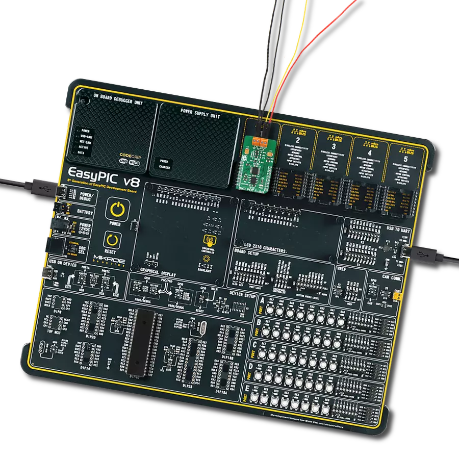
Start by selecting your development board and Click board™. Begin with the EasyAVR v7 as your development board.


Track your results in real time
Application Output
1. Application Output - In Debug mode, the 'Application Output' window enables real-time data monitoring, offering direct insight into execution results. Ensure proper data display by configuring the environment correctly using the provided tutorial.

2. UART Terminal - Use the UART Terminal to monitor data transmission via a USB to UART converter, allowing direct communication between the Click board™ and your development system. Configure the baud rate and other serial settings according to your project's requirements to ensure proper functionality. For step-by-step setup instructions, refer to the provided tutorial.

3. Plot Output - The Plot feature offers a powerful way to visualize real-time sensor data, enabling trend analysis, debugging, and comparison of multiple data points. To set it up correctly, follow the provided tutorial, which includes a step-by-step example of using the Plot feature to display Click board™ readings. To use the Plot feature in your code, use the function: plot(*insert_graph_name*, variable_name);. This is a general format, and it is up to the user to replace 'insert_graph_name' with the actual graph name and 'variable_name' with the parameter to be displayed.

Software Support
Library Description
This library contains API for DIGI POT 9 Click driver.
Key functions:
digipot9_generic_write- This function writes two data bytes to the selected command and address by using SPI serial interfacedigipot9_generic_read- This function reads two data bytes from the selected command and address by using SPI serial interfacedigipot9_set_wiper_1- This function sets wiper 1 to desired value
Open Source
Code example
The complete application code and a ready-to-use project are available through the NECTO Studio Package Manager for direct installation in the NECTO Studio. The application code can also be found on the MIKROE GitHub account.
/*!
 * @file main.c
 * @brief DIGIPOT9 Click example
 *
 * # Description
 * This example demonstrates the use of DIGI POT 9 Click board.
 *
 * The demo application is composed of two sections :
 *
 * ## Application Init
 * Initializes the driver and makes an initial log.
 *
 * ## Application Task
 * Iterates through the entire wiper range and sets both wipers to
 * the iterator value once per second.
 * The current wiper position will be displayed on the USB UART.
 *
 * @author Stefan Filipovic
 *
 */

#include "board.h"
#include "log.h"
#include "digipot9.h"

static digipot9_t digipot9;
static log_t logger;

void application_init ( void )
{
    log_cfg_t log_cfg;            /**< Logger config object. */
    digipot9_cfg_t digipot9_cfg;  /**< Click config object. */

    /**
     * Logger initialization.
     * Default baud rate: 115200
     * Default log level: LOG_LEVEL_DEBUG
     * @note If USB_UART_RX and USB_UART_TX
     * are defined as HAL_PIN_NC, you will
     * need to define them manually for log to work.
     * See @b LOG_MAP_USB_UART macro definition for detailed explanation.
     */
    LOG_MAP_USB_UART( log_cfg );
    log_init( &logger, &log_cfg );
    log_info( &logger, " Application Init " );

    // Click initialization.

    digipot9_cfg_setup( &digipot9_cfg );
    DIGIPOT9_MAP_MIKROBUS( digipot9_cfg, MIKROBUS_1 );
    err_t init_flag  = digipot9_init( &digipot9, &digipot9_cfg );
    if ( SPI_MASTER_ERROR == init_flag )
    {
        log_error( &logger, " Application Init Error. " );
        log_info( &logger, " Please, run program again... " );

        for ( ; ; );
    }

    digipot9_default_cfg ( &digipot9 );
    log_info( &logger, " Application Task " );
}

void application_task ( void )
{
    for ( uint16_t cnt = DIGIPOT9_WIPER_ZERO_SCALE; cnt <= DIGIPOT9_WIPER_FULL_SCALE; cnt += 50 )
    {
        digipot9_set_wiper_1 ( &digipot9, cnt );
        digipot9_set_wiper_2 ( &digipot9, cnt );
        log_printf( &logger, " * Wipers position set to %u *\r\n", cnt );

        Delay_ms ( 1000 );
    }
}

int main ( void )
{
    /* Do not remove this line or clock might not be set correctly. */
    #ifdef PREINIT_SUPPORTED
    preinit();
    #endif

    application_init( );

    for ( ; ; )
    {
        application_task( );
    }

    return 0;
}

// ------------------------------------------------------------------------ END