Break free from the constraints of traditional wired connections with BT121 and ATmega644P
Say goodbye to wires and hello to limitless possibilities

Published Nov 09, 2023
Click board™
BT Click
Dev. board
EasyAVR v7
Compiler
NECTO Studio
MCU
ATmega644P
Simplify your life and streamline your devices with our Bluetooth solution. It's time to connect smarter, not harder.
A
A
Hardware Overview
How does it work?
BT Click is based on the BT121, a dual-mode Bluetooth Smart Ready module solution that gives unparalleled flexibility to integrate Bluetooth Smart and Bluetooth Basic Rate/Enhanced Data Rate (BR/EDR) wireless technologies from Silicon Labs. It contains a high-performance Bluetooth radio, a low-power ARM Cortex MCU, and a Bluegiga Bluetooth Smart Ready stack software, marking it an extremely easy-to-use device. Also, it contains two configurable power-saving modes. Power Mode 1 is a shallow sleep state with all clocks and peripherals running but with the processor core stopped, while Power Mode 2 is a deep sleep state in which most peripheral devices and system clocks are Power-Down states. The BT121 module generates all the required clock signals internally. The clocks used by the internal MCU and external peripherals are synchronized to an internal 32.768kHz crystal connected to the internal RTC, which is always available to wake up the module. It will take approximately two seconds for the RTC oscillator to stabilize after power is connected. To avoid this delay, it's recommended not to turn off the power supply of the BT121 but to set the module into the lowest power mode,
providing the smallest current consumption. This Click board™ uses the UART communication interface as its default communication protocol that supports all standard baud rates up to 4Mbps. It also allows the user to use the I2C interface to configure the module and write the library himself. In addition to standard UART TX/RX pins, it also has UART RTS/CTS pins routed on the CS and PWM pins of the mikroBUS™ socket recommended for every application for reliable data transfer. It is necessary to mention the way this Click board™ works so that the user can use it correctly. In the example code that MIKROE offers to its users, the Serial Bluetooth Terminal Android application was used. By clicking on the given link, the user is directed to the free Android application on the Play Store that needs to be downloaded and installed to pair his device with BT Click. Only after successful pairing the BT Click will be visible in the Serial Bluetooth Terminal Android application. The BT121 module has built-in firmware that can use the module Update feature. The module can be updated through the UART interface by holding the built-in ARM® Cortex® MCU of the BT121 module in a Reset state via the RST pin, which typically
will free the UART communication lines to be used by the Device Firmware Update protocol (DFU). DFU protocol contains commands and events related to controlling firmware updates over the configured host interface and is available only when the module has been booted into DFU Mode. In addition to all features, the BT Click also has additional components such as 2 LED indicators as well as several onboard pushbuttons. Based on the example code, the blue LED labeled as LED1 indicates the successfully established connection visually, and the red LED labeled as LED 2 reports that establishing the connection is unsuccessful. The onboard pushbuttons don't have a precisely defined function. It can be configured to operate as a standard general-purpose digital I/O's, and they are left to the user to configure them according to their needs. This Click board™ can be operated only with a 3.3V logic voltage level. The board must perform appropriate logic voltage level conversion before using MCUs with different logic levels. Also, it comes equipped with a library containing functions and an example code that can be used as a reference for further development.

Features overview
Development board
EasyAVR v7 is the seventh generation of AVR development boards specially designed for the needs of rapid development of embedded applications. It supports a wide range of 16-bit AVR microcontrollers from Microchip and has a broad set of unique functions, such as a powerful onboard mikroProg programmer and In-Circuit debugger over USB. The development board is well organized and designed so that the end-user has all the necessary elements in one place, such as switches, buttons, indicators, connectors, and others. With four different connectors for each port, EasyAVR v7 allows you to connect accessory boards, sensors, and custom electronics more
efficiently than ever. Each part of the EasyAVR v7 development board contains the components necessary for the most efficient operation of the same board. An integrated mikroProg, a fast USB 2.0 programmer with mikroICD hardware In-Circuit Debugger, offers many valuable programming/debugging options and seamless integration with the Mikroe software environment. Besides it also includes a clean and regulated power supply block for the development board. It can use a wide range of external power sources, including an external 12V power supply, 7-12V AC or 9-15V DC via DC connector/screw terminals, and a power source via the USB Type-B (USB-B)
connector. Communication options such as USB-UART and RS-232 are also included, alongside the well-established mikroBUS™ standard, three display options (7-segment, graphical, and character-based LCD), and several different DIP sockets which cover a wide range of 16-bit AVR MCUs. EasyAVR v7 is an integral part of the Mikroe ecosystem for rapid development. Natively supported by Mikroe software tools, it covers many aspects of prototyping and development thanks to a considerable number of different Click boards™ (over a thousand boards), the number of which is growing every day.

Microcontroller Overview
MCU Card / MCU

Architecture
AVR
MCU Memory (KB)
64
Silicon Vendor
Microchip
Pin count
40
RAM (Bytes)
4096
Used MCU Pins
mikroBUS™ mapper
Take a closer look
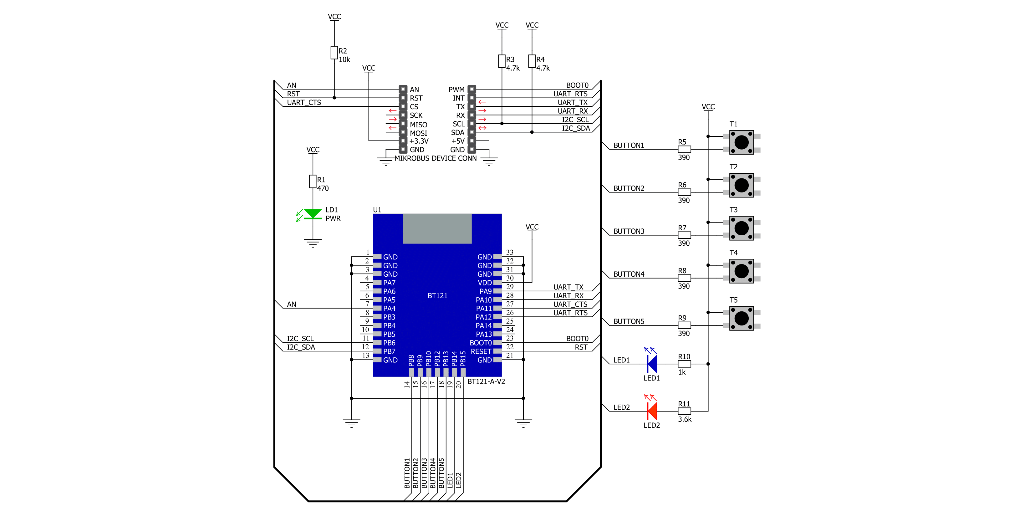
Click board™ Schematic
Step by step
Project assembly

Start by selecting your development board and Click board™. Begin with the EasyAVR v7 as your development board.


Software Support
Library Description
This library contains API for BT Click driver.
Key functions:
bt_set_local_name- This function sets the local name of the device.bt_send_package- This function sends a data package to the click board.bt_read_package- This function waits for the command or event type of message to arrive and then reads the complete message and stores it to pkg structure.
Open Source
Code example
The complete application code and a ready-to-use project are available through the NECTO Studio Package Manager for direct installation in the NECTO Studio. The application code can also be found on the MIKROE GitHub account.
/*!
 * @file main.c
 * @brief BT Click Example.
 *
 * # Description
 * This example demonstrates the use of BT Click board.
 *
 * The demo application is composed of two sections :
 *
 * ## Application Init
 * Initializes the driver and configures the Click board.
 *
 * ## Application Task
 * Handles most of the events required for this example, the packages of events not
 * supported in this example will be just displayed on the USB UART.
 * The event handler will display all messages sent from the remote device on the USB UART and
 * send back the predefined response message "DONE".
 * There are two specific commands which can be sent from the remote device:
 * "led blink" - calls @b bt_led_blink function for a 5 seconds time period.
 * "check buttons" - calls @b bt_check_buttons function.
 *
 * ## Additional Function
 * - static void bt_event_handler ( bt_t *ctx )
 * - static void bt_led_blink ( bt_t *ctx )
 * - static void bt_check_buttons ( bt_t *ctx )
 *
 * @note
 * We have used the Serial Bluetooth Terminal smartphone application for the test.
 * A smartphone and the Click board must be paired in order to exchange messages with each other.
 *
 * @author Stefan Filipovic
 *
 */

#include "board.h"
#include "log.h"
#include "bt.h"

static bt_t bt;
static log_t logger;

/**
 * @brief BT event handler function.
 * @details This function handles most of the events required for this example.
 * It will respond to all messages sent from the remote device with a message "DONE".
 * There are two specific commands which can be sent from the remote device:
 * "led blink" - calls @b bt_led_blink function for a 5 seconds time frame.
 * "check buttons" - calls @b bt_check_buttons function.
 * @param[in] ctx : Click context object.
 * See #bt_t object definition for detailed explanation.
 * @return None.
 * @note The Click board must be configured and the remote device must be connected to it.
 */
static void bt_event_handler ( bt_t *ctx );

/**
 * @brief BT led blink function.
 * @details This function toggles the LEDs on the Click board.
 * @param[in] ctx : Click context object.
 * See #bt_t object definition for detailed explanation.
 * @param[in] time_s : LED blinking time in seconds.
 * @return None.
 * @note None.
 */
static void bt_led_blink ( bt_t *ctx, uint16_t time_s );

/**
 * @brief BT check buttons function.
 * @details This function checks all buttons state and displays the result on the USB UART.
 * @param[in] ctx : Click context object.
 * See #bt_t object definition for detailed explanation.
 * @return None.
 * @note None.
 */
static void bt_check_buttons ( bt_t *ctx );

void application_init ( void )
{
    log_cfg_t log_cfg;  /**< Logger config object. */
    bt_cfg_t bt_cfg;    /**< Click config object. */

    /**
     * Logger initialization.
     * Default baud rate: 115200
     * Default log level: LOG_LEVEL_DEBUG
     * @note If USB_UART_RX and USB_UART_TX
     * are defined as HAL_PIN_NC, you will
     * need to define them manually for log to work.
     * See @b LOG_MAP_USB_UART macro definition for detailed explanation.
     */
    LOG_MAP_USB_UART( log_cfg );
    log_init( &logger, &log_cfg );
    Delay_ms ( 100 );
    log_info( &logger, " Application Init " );

    // Click initialization.

    bt_cfg_setup( &bt_cfg );
    BT_MAP_MIKROBUS( bt_cfg, MIKROBUS_1 );
    err_t init_flag  = bt_init( &bt, &bt_cfg );
    if ( UART_ERROR == init_flag )
    {
        log_error( &logger, " Application Init Error. " );
        log_info( &logger, " Please, run program again... " );

        for ( ; ; );
    }

    log_printf( &logger, " Default Config : %s\r\n\n", ( char * )
                         ( BT_OK == bt_default_cfg ( &bt ) ? "OK" : "FAIL" ) );

    log_printf( &logger, " Set Local Name : %s\r\n\n", ( char * )
                        ( BT_OK == bt_set_local_name ( &bt, "MikroE - BT Click" ) ? "OK" : "FAIL" ) );

    log_printf( &logger, " Delete Bondings : %s\r\n\n", ( char * )
                        ( BT_OK == bt_delete_bondings ( &bt ) ? "OK" : "FAIL" ) );

    log_printf( &logger, " Set Bondable Mode : %s\r\n\n", ( char * )
                        ( BT_OK == bt_set_bondable_mode ( &bt, BT_SM_SET_BONDABLE_ALLOWED ) ? "OK" : "FAIL" ) );

    log_printf( &logger, " Set GAP Mode : %s\r\n\n", ( char * )
                        ( BT_OK == bt_set_gap_mode ( &bt, BT_GAP_MODE_CONNECTABLE,
                                                          BT_GAP_MODE_DISCOVERABLE,
                                                          BT_GAP_MODE_NOT_LIMITED ) ? "OK" : "FAIL" ) );

    log_printf( &logger, " RFCOMM Start Server : %s\r\n\n", ( char * )
                        ( BT_OK == bt_rfcomm_start_server ( &bt, BT_RFCOMM_SERVER_DEF_SDP_ID,
                                                                 BT_RFCOMM_SERVER_DEF_STREAM_DEST ) ? "OK" : "FAIL" ) );

    log_info( &logger, " Application Task " );
}

void application_task ( void )
{
    bt_event_handler( &bt );
}

int main ( void )
{
    /* Do not remove this line or clock might not be set correctly. */
    #ifdef PREINIT_SUPPORTED
    preinit();
    #endif

    application_init( );

    for ( ; ; )
    {
        application_task( );
    }

    return 0;
}

static void bt_event_handler ( bt_t *ctx )
{
    bt_package_t pkg;

    if ( BT_OK == bt_read_package ( ctx, &pkg ) )
    {
        if ( BT_MSG_TYPE_EVENT == pkg.msg_type )
        {
            if ( BT_MSG_CLASS_ENDPOINT == pkg.msg_class )
            {
                if ( BT_MSG_ID_EVT_ENDPOINT_DATA == pkg.msg_id )
                {
                    log_printf( &logger, " The endpoint 0x%.2X received data: ", ( uint16_t ) pkg.payload[ 0 ] );
                    for ( uint8_t cnt = 0; cnt < pkg.payload[ 1 ]; cnt++ )
                    {
                        log_printf( &logger, "%c", pkg.payload[ cnt + 2 ] );
                    }
                    if ( memcmp ( &pkg.payload[ 2 ], "check buttons", 13 ) == 0 )
                    {
                        bt_check_buttons( ctx );
                    }
                    if ( memcmp ( &pkg.payload[ 2 ], "led blink", 9 ) == 0 )
                    {
                        bt_led_blink( ctx, 5 );
                    }
                    log_printf( &logger, " Sending the message \"DONE\" back to the remote device : %s\r\n\n", ( char * )
                                        ( BT_OK == bt_endpoint_send_data ( &bt, &pkg.payload[ 0 ], "DONE\r\n" ) ? "OK" : "FAIL" ) );
                }
            }
            else if ( BT_MSG_CLASS_CONNECTION == pkg.msg_class )
            {
                if ( BT_MSG_ID_EVT_CONNECTION_OPENED == pkg.msg_id )
                {
                    log_printf( &logger, " Connection 0x%.2X: OPENED\r\n", ( uint16_t ) pkg.payload[ 7 ]  );
                    log_printf( &logger, " Address of remote device: " );
                    log_printf( &logger, "%.2X:%.2X:%.2X:%.2X:%.2X:%.2X\r\n", ( uint16_t ) pkg.payload[ 5 ],
                                                                              ( uint16_t ) pkg.payload[ 4 ],
                                                                              ( uint16_t ) pkg.payload[ 3 ],
                                                                              ( uint16_t ) pkg.payload[ 2 ],
                                                                              ( uint16_t ) pkg.payload[ 1 ],
                                                                              ( uint16_t ) pkg.payload[ 0 ] );
                    log_printf( &logger, " Role of the local device : %s\r\n", ( char * )
                                        ( 0 == pkg.payload[ 6 ] ? "Peripheral" : "Central" ) );

                    log_printf( &logger, " Bonded : %s\r\n\n",
                                         0xFF == pkg.payload[ 8 ] ? "NO" : "YES" );
                }
                else if ( BT_MSG_ID_EVT_CONNECTION_CLOSED == pkg.msg_id )
                {
                    log_printf( &logger, " Connection 0x%.2X: CLOSED\r\n\n", ( uint16_t ) pkg.payload[ 2 ] );
                }
            }
            else if ( BT_MSG_CLASS_SM == pkg.msg_class )
            {
                if ( BT_MSG_ID_EVT_SM_BONDED == pkg.msg_id )
                {
                    log_printf( &logger, " Connection 0x%.2X: %s\r\n\n",
                                         ( uint16_t ) pkg.payload[ 0 ], ( char * )
                                         ( 0xFF != pkg.payload[ 1 ] ? "BONDED" : "NOT BONDED" ) );
                }
            }
            else if ( BT_MSG_CLASS_RFCOMM == pkg.msg_class )
            {
                if ( BT_MSG_ID_EVT_RFCOMM_OPENED == pkg.msg_id )
                {
                    log_printf( &logger, " RFCOMM connection 0x%.2X: OPENED\r\n", ( uint16_t ) pkg.payload[ 0 ] );
                    log_printf( &logger, " Address of remote device: " );
                    log_printf( &logger, "%.2X:%.2X:%.2X:%.2X:%.2X:%.2X\r\n\n", ( uint16_t ) pkg.payload[ 6 ],
                                                                                ( uint16_t ) pkg.payload[ 5 ],
                                                                                ( uint16_t ) pkg.payload[ 4 ],
                                                                                ( uint16_t ) pkg.payload[ 3 ],
                                                                                ( uint16_t ) pkg.payload[ 2 ],
                                                                                ( uint16_t ) pkg.payload[ 1 ] );
                }
                else if ( BT_MSG_ID_EVT_RFCOMM_MODEM_STATUS == pkg.msg_id )
                {
                    log_printf( &logger, " RFCOMM connection 0x%.2X status: 0x%.2X\r\n\n",
                                         ( uint16_t ) pkg.payload[ 0 ],
                                         ( uint16_t ) pkg.payload[ 1 ] );
                }
            }
            else
            {
                log_printf( &logger, " Message Type: 0x%.2X\r\n", ( uint16_t ) pkg.msg_type );
                log_printf( &logger, " Payload len: 0x%.2X\r\n", ( uint16_t ) pkg.payload_len );
                log_printf( &logger, " Message Class: 0x%.2X\r\n", ( uint16_t ) pkg.msg_class );
                log_printf( &logger, " Message ID: 0x%.2X\r\n", ( uint16_t ) pkg.msg_id );

                if ( pkg.payload_len > 0 )
                {
                    log_printf( &logger, " Payload: " );
                    for ( uint8_t cnt = 0; cnt < pkg.payload_len; cnt++ )
                    {
                        log_printf( &logger, " 0x%.2X ", ( uint16_t ) pkg.payload[ cnt ] );
                    }
                    log_printf( &logger, "\r\n\n" );
                }
            }
        }
        else
        {
            log_error( &logger, " No event message type.\r\n" );
            log_printf( &logger, " Message Type: 0x%.2X\r\n", ( uint16_t ) pkg.msg_type );
        }
    }
    else
    {
        log_error( &logger, " Reading package.\r\n" );
    }
    Delay_ms ( 100 );
}

static void bt_led_blink ( bt_t *ctx, uint16_t time_s )
{
    for ( uint16_t cnt = 0; cnt < time_s; cnt++ )
    {
        bt_hardware_write_gpio ( ctx, BT_HARDWARE_CONFIG_PORT_B,
                                      BT_HARDWARE_ALL_LEDS_PIN_MASK,
                                      BT_HARDWARE_ALL_LEDS_PIN_MASK );
        Delay_ms ( 500 );
        bt_hardware_write_gpio ( ctx, BT_HARDWARE_CONFIG_PORT_B,
                                      BT_HARDWARE_ALL_LEDS_PIN_MASK,
                                      0 );
        Delay_ms ( 500 );
    }
}

static void bt_check_buttons ( bt_t *ctx )
{
    uint16_t port_data = 0;

    if ( BT_OK == bt_hardware_read_gpio ( ctx, BT_HARDWARE_CONFIG_PORT_B,
                                               BT_HARDWARE_ALL_BUTTONS_PIN_MASK,
                                               &port_data ) )
    {
        log_printf( &logger, "\r\n Buttons pressed : - " );

        if ( port_data & BT_HARDWARE_BUTTON1_PIN_MASK )
        {
            log_printf( &logger, "1 - " );
        }

        if ( port_data & BT_HARDWARE_BUTTON2_PIN_MASK )
        {
            log_printf( &logger, "2 - " );
        }

        if ( port_data & BT_HARDWARE_BUTTON3_PIN_MASK )
        {
            log_printf( &logger, "3 - " );
        }

        if ( port_data & BT_HARDWARE_BUTTON4_PIN_MASK )
        {
            log_printf( &logger, "4 - " );
        }

        if ( port_data & BT_HARDWARE_BUTTON5_PIN_MASK )
        {
            log_printf( &logger, "5 - " );
        }

        if ( ( port_data & BT_HARDWARE_ALL_BUTTONS_PIN_MASK ) == 0 )
        {
            log_printf( &logger, "None - " );
        }
        log_printf( &logger, "\r\n\n" );
    }
    else
    {
        log_error( &logger, " Reading GPIO.\r\n" );
    }
}

// ------------------------------------------------------------------------ END


