Take action with STC31 and PIC32MZ2048EFH100 to reduce CO2 levels for healthier living
Stay aware of your environment

Published Aug 30, 2023
Click board™
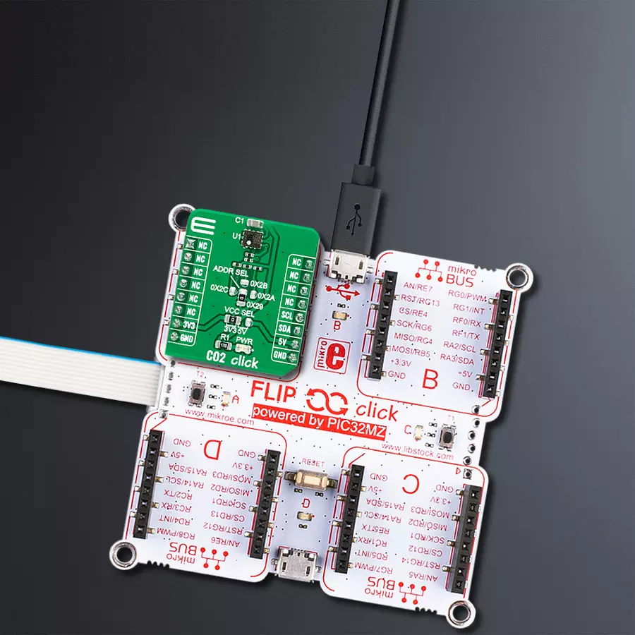
CO2 Click
Dev. board
Flip&Click PIC32MZ
Compiler
NECTO Studio
MCU
PIC32MZ2048EFH100
Ensure the safety of your residential environments with a reliable high CO2 concentration monitoring solution
A
A
Hardware Overview
How does it work?
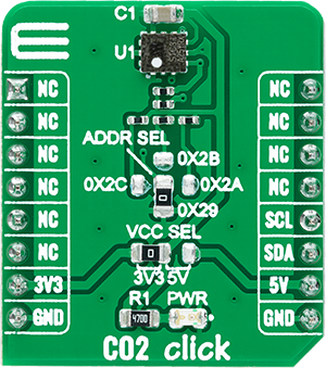
CO2 Click is based on the STC31, a gas concentration sensor for high-range, accurate CO2 measurements designed for high-volume applications from Sensirion. The STC31 is based on a revolutionized thermal conductivity measurement principle, which results in superior repeatability and long-term stability. The sensor offers ultra-low power consumption by relying on thermal conductivity technology, making the STC31 the perfect choice for applications where reliability is vital. The accuracy of the STC31 is 0.5 vol% and ±3% of the measured value, while the sensor response time is faster than 1 second.
The outstanding performance of these sensors is based on Sensirion’s patented CMOSens® Technology, which combines the sensor element, signal processing, and digital calibration on a small CMOS chip. The well-proven CMOSens® Technology is ideal for demanding and cost-sensitive OEM applications. CO2 Click communicates with MCU using the standard I2C 2-Wire interface to read data and configure settings, supporting Standard Mode operation with a clock frequency up to 100kHz, Fast Mode up to 400kHz, and Fast Mode Plus up to 1MHz. Besides, it also allows the choice of the three least
significant bits of its I2C slave address by positioning the SMD jumper labeled as ADDR SEL to an appropriate position, providing the user with a choice of 4 I2C Slave addresses. This Click board™ can operate with either 3.3V or 5V logic voltage levels selected via the VCC SEL jumper. This way, both 3.3V and 5V capable MCUs can use the communication lines properly. Also, this Click board™ comes equipped with a library containing easy-to-use functions and an example code that can be used as a reference for further development.


Features overview
Development board
Flip&Click PIC32MZ is a compact development board designed as a complete solution that brings the flexibility of add-on Click boards™ to your favorite microcontroller, making it a perfect starter kit for implementing your ideas. It comes with an onboard 32-bit PIC32MZ microcontroller, the PIC32MZ2048EFH100 from Microchip, four mikroBUS™ sockets for Click board™ connectivity, two USB connectors, LED indicators, buttons, debugger/programmer connectors, and two headers compatible with Arduino-UNO pinout. Thanks to innovative manufacturing technology,
it allows you to build gadgets with unique functionalities and features quickly. Each part of the Flip&Click PIC32MZ development kit contains the components necessary for the most efficient operation of the same board. In addition, there is the possibility of choosing the Flip&Click PIC32MZ programming method, using the chipKIT bootloader (Arduino-style development environment) or our USB HID bootloader using mikroC, mikroBasic, and mikroPascal for PIC32. This kit includes a clean and regulated power supply block through the USB Type-C (USB-C) connector. All communication
methods that mikroBUS™ itself supports are on this board, including the well-established mikroBUS™ socket, user-configurable buttons, and LED indicators. Flip&Click PIC32MZ development kit allows you to create a new application in minutes. Natively supported by Mikroe software tools, it covers many aspects of prototyping thanks to a considerable number of different Click boards™ (over a thousand boards), the number of which is growing every day.

Microcontroller Overview
MCU Card / MCU

Architecture
PIC32
MCU Memory (KB)
2048
Silicon Vendor
Microchip
Pin count
100
RAM (Bytes)
524288
Used MCU Pins
mikroBUS™ mapper
Take a closer look
Click board™ Schematic

Step by step
Project assembly

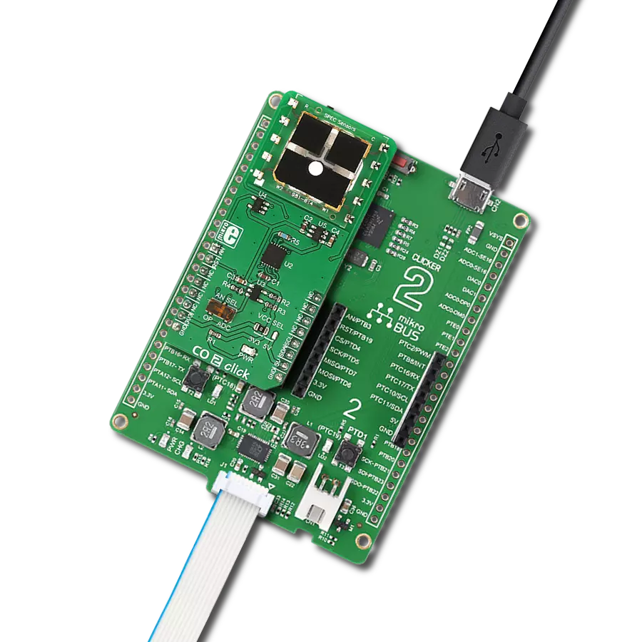
Start by selecting your development board and Click board™. Begin with the Flip&Click PIC32MZ as your development board.


Track your results in real time
Application Output
1. Application Output - In Debug mode, the 'Application Output' window enables real-time data monitoring, offering direct insight into execution results. Ensure proper data display by configuring the environment correctly using the provided tutorial.

2. UART Terminal - Use the UART Terminal to monitor data transmission via a USB to UART converter, allowing direct communication between the Click board™ and your development system. Configure the baud rate and other serial settings according to your project's requirements to ensure proper functionality. For step-by-step setup instructions, refer to the provided tutorial.

3. Plot Output - The Plot feature offers a powerful way to visualize real-time sensor data, enabling trend analysis, debugging, and comparison of multiple data points. To set it up correctly, follow the provided tutorial, which includes a step-by-step example of using the Plot feature to display Click board™ readings. To use the Plot feature in your code, use the function: plot(*insert_graph_name*, variable_name);. This is a general format, and it is up to the user to replace 'insert_graph_name' with the actual graph name and 'variable_name' with the parameter to be displayed.

Software Support
Library Description
This library contains API for CO2 Click driver.
Key functions:
co2_get_id- Read device and serial ID'sco2_set_reference- Set device refrence values for gas calculationco2_read_gas- Read CO2 concentration and temperature value
Open Source
Code example
The complete application code and a ready-to-use project are available through the NECTO Studio Package Manager for direct installation in the NECTO Studio. The application code can also be found on the MIKROE GitHub account.
/*!
 * @file main.c
 * @brief CO2 Click example
 *
 * # Description
 * This example showcases ability of Click board. It reads ID's
 * configures device for operation work and reads CO2 gas
 * concentration in air and temperature of IC every second.
 *
 * The demo application is composed of two sections :
 *
 * ## Application Init
 * Initialization of host communication modules (UART, I2C).
 * Checks device and serial ID's from device. Then calls default
 * configuration function that resets device, self tests it selft
 * and configures for measuring CO2 concentration from air.
 *
 * ## Application Task
 * Reads air CO2 gas concentration in precentage and IC's
 * temperature in deg Celzius in span of 1 second and logs
 * data to UART Terminal.
 *
 * @author Luka Filipovic
 *
 */

#include "board.h"
#include "log.h"
#include "co2.h"

#define CO2_AIR_HUMIDITY 40/*< Relative air humidity in % */
#define CO2_AIR_PRESSURE 1008/*< Relative air pressure in mBar */

static co2_t co2;
static co2_cfg_t co2_cfg;
static log_t logger;

void application_init ( void )
{
    log_cfg_t log_cfg;  /**< Logger config object. */

    /**
     * Logger initialization.
     * Default baud rate: 115200
     * Default log level: LOG_LEVEL_DEBUG
     * @note If USB_UART_RX and USB_UART_TX
     * are defined as HAL_PIN_NC, you will
     * need to define them manually for log to work.
     * See @b LOG_MAP_USB_UART macro definition for detailed explanation.
     */
    LOG_MAP_USB_UART( log_cfg );
    log_init( &logger, &log_cfg );
    log_info( &logger, " Application Init " );

    // Click initialization.
    co2_cfg_setup( &co2_cfg );
    CO2_MAP_MIKROBUS( co2_cfg, MIKROBUS_1 );
    err_t init_flag = co2_init( &co2, &co2_cfg );
    if ( init_flag == I2C_MASTER_ERROR )
    {
        log_error( &logger, " Application Init Error. " );
        log_info( &logger, " Please, run program again... " );

        for ( ; ; );
    }

    init_flag = co2_get_id( &co2 );

    if ( ( init_flag < 0 ) && ( co2.device_id != CO2_DEVICE_ID ) )
    {
        log_error( &logger, "ID" );
    }
    else
    {
        log_printf( &logger, " > Device ID: 0x%.8lX\r\n", co2.device_id );
        log_printf( &logger, " > Serial ID: 0x%.8lX%.8lX\r\n", co2.serial_id[ 0 ], co2.serial_id[ 1 ] );
    }

    init_flag = co2_default_cfg ( &co2 );

    if ( init_flag < 0 )
    {
        log_error( &logger, " Default configuration. " );
        log_info( &logger, " Please, run program again... " );

        for ( ; ; );
    }

    //Set reference values for device to calculate gas concentartion.
    if ( CO2_OK != co2_set_reference( &co2, CO2_AIR_HUMIDITY, CO2_AIR_PRESSURE ) )
    {
        log_error( &logger, " Reference values." );
    }

    Delay_ms ( 1000 );
    log_info( &logger, " Application Task " );
}

void application_task ( void )
{
    float gas_data = 0;
    float temp_data = 0;

    if ( CO2_OK == co2_read_gas( &co2, &gas_data, &temp_data ) )
    {
        log_printf( &logger, " > CO2[%%]: %.2f\r\n", gas_data );
        log_printf( &logger, " > Temperature[degC]: %.2f\r\n", temp_data );
        Delay_ms ( 1000 );
    }

    Delay_ms ( 1 );
}

int main ( void )
{
    /* Do not remove this line or clock might not be set correctly. */
    #ifdef PREINIT_SUPPORTED
    preinit();
    #endif

    application_init( );

    for ( ; ; )
    {
        application_task( );
    }

    return 0;
}

// ------------------------------------------------------------------------ END