Experience the efficiency of our 4-20mA current loop solution with DAC161S997 and ATmega324P
Enhance your process automation

Published Aug 09, 2023
Click board™
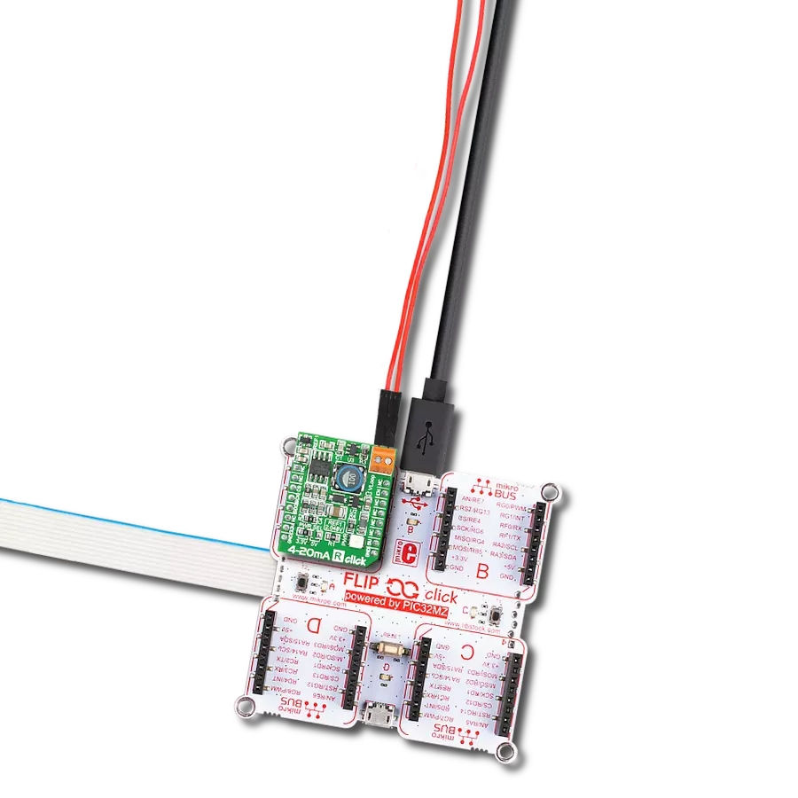
4-20mA T 2 Click
Dev. board
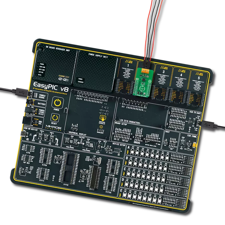
EasyAVR v7
Compiler
NECTO Studio
MCU
ATmega324P
Experience precise signal transmission with our advanced analog current loop transmitter, which provides seamless connectivity and compatibility with various industrial applications
A
A
Hardware Overview
How does it work?
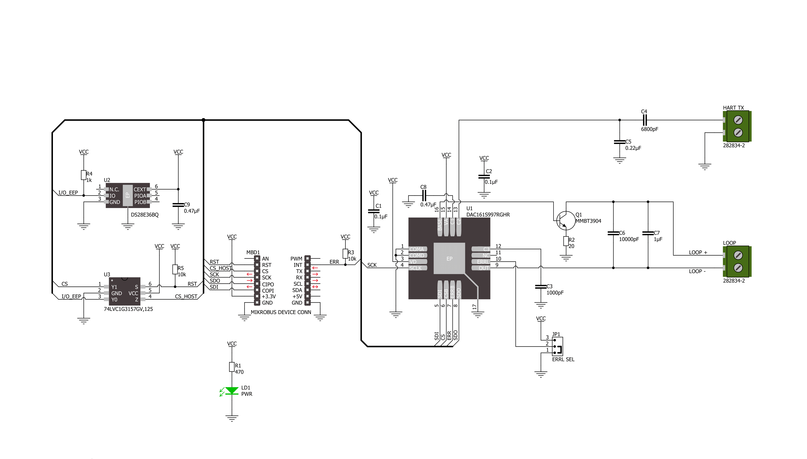
4-20mA T 2 Click is based on the DAC161S997, a low-power 16-bit ΣΔ digital-to-analog converter (DAC) from Texas Instruments, realized as a ΣΔ modulator. Next to ΣΔ DAC, the DAC161S997 also contains an internal ultra-low power voltage reference and an internal oscillator to reduce power and component count in compact loop-powered applications. This architecture, where DAC's output current represents a multiplied copy of the filtered modulator output, ensures an excellent linearity performance while minimizing the device's power consumption. In addition to an industry-standard 4-20 mA current loop over the LOOP terminal, the DAC161S997 also has the possibility of a simple Highway Addressable
Remote Transducer (HART) modulator interfacing through an onboard HART TX terminal. It allows the injection of FSK-modulated digital data into the 4-20mA current loop. This Click board™ communicates with MCU using a 4-wire SPI serial interface with a maximum frequency of 10MHz, for data transfer and configuration of the DAC functions. The DAC161S997 supports both Mode 0 and Mode 3 of the SPI protocol. 4-20mA T 2 Click comes with an additional feature, as an interrupt, available on the ERR pin of the mikroBUS™ socket, the loop-error detection/reporting feature. By default, the DAC161S997 detects and reports several types of errors: loop error, SPI timeout error (channel error), frame error, and alarm current. In
the case of a fault condition or during the initial Power-Up sequence, the DAC161S997 will output current in either the upper or lower error current band. The band's choice is user-selectable via the appropriate position of an onboard jumper ERRL SEL, while the current error value is programmable through the SPI interface. This Click board™ can be operated only with a 3.3V logic voltage level. The board must perform appropriate logic voltage level conversion before using MCUs with different logic levels. Also, it comes equipped with a library containing functions and an example code that can be used, as a reference, for further development.

Features overview
Development board
EasyAVR v7 is the seventh generation of AVR development boards specially designed for the needs of rapid development of embedded applications. It supports a wide range of 16-bit AVR microcontrollers from Microchip and has a broad set of unique functions, such as a powerful onboard mikroProg programmer and In-Circuit debugger over USB. The development board is well organized and designed so that the end-user has all the necessary elements in one place, such as switches, buttons, indicators, connectors, and others. With four different connectors for each port, EasyAVR v7 allows you to connect accessory boards, sensors, and custom electronics more
efficiently than ever. Each part of the EasyAVR v7 development board contains the components necessary for the most efficient operation of the same board. An integrated mikroProg, a fast USB 2.0 programmer with mikroICD hardware In-Circuit Debugger, offers many valuable programming/debugging options and seamless integration with the Mikroe software environment. Besides it also includes a clean and regulated power supply block for the development board. It can use a wide range of external power sources, including an external 12V power supply, 7-12V AC or 9-15V DC via DC connector/screw terminals, and a power source via the USB Type-B (USB-B)
connector. Communication options such as USB-UART and RS-232 are also included, alongside the well-established mikroBUS™ standard, three display options (7-segment, graphical, and character-based LCD), and several different DIP sockets which cover a wide range of 16-bit AVR MCUs. EasyAVR v7 is an integral part of the Mikroe ecosystem for rapid development. Natively supported by Mikroe software tools, it covers many aspects of prototyping and development thanks to a considerable number of different Click boards™ (over a thousand boards), the number of which is growing every day.

Microcontroller Overview
MCU Card / MCU

Architecture
AVR
MCU Memory (KB)
32
Silicon Vendor
Microchip
Pin count
40
RAM (Bytes)
2048
Used MCU Pins
mikroBUS™ mapper
Take a closer look
Click board™ Schematic
Step by step
Project assembly

Start by selecting your development board and Click board™. Begin with the EasyAVR v7 as your development board.


Software Support
Library Description
This library contains API for 4-20mA T 2 Click driver.
Key functions:
c420mat2_set_output_current- 4-20mA T 2 set output current functionc420mat2_get_status- 4-20mA T 2 set status functionc420mat2_set_lower_limit- 4-20mA T 2 set lower limit function
Open Source
Code example
The complete application code and a ready-to-use project are available through the NECTO Studio Package Manager for direct installation in the NECTO Studio. The application code can also be found on the MIKROE GitHub account.
/*!
 * @file main.c
 * @brief 4-20mA T 2 Click example
 *
 * # Description
 * This example demonstrates the use of 4-20mA T 2 Click board™.
 * This driver provides functions to configure
 * analog output current transfer over an industry standard 4-20mA current loop.
 *
 * The demo application is composed of two sections :
 *
 * ## Application Init
 * Initialization of SPI module and log UART.
 * After driver initialization, default settings turn on the device.
 *
 * ## Application Task
 * This example demonstrates the use of the 4-20mA T 2 Click board™.
 * This example periodically changes the analog output current transfer
 * from 4mA to 20mA and display status every 5 seconds.
 * Results are being sent to the UART Terminal, where you can track their changes.
 *
 * @author Nenad Filipovic
 *
 */

#include "board.h"
#include "log.h"
#include "c420mat2.h"

static c420mat2_t c420mat2;
static log_t logger;
static c420mat2_status_t status;

void display_status ( void )
{
    log_printf( &logger, " Status: \r\n" );
    if ( C420MAT2_STATUS_ERROR == status.ferr_sts )
    {
        log_printf( &logger, " - A frame error has occurred.\r\n" );
    }
    else
    {
        log_printf( &logger, " - No frame error occurred.\r\n" );
    }

    if ( C420MAT2_STATUS_ERROR == status.spi_timeout_err )
    {
        log_printf( &logger, " - The SPI interface has not received a valid command.\r\n" );
    }
    else
    {
        log_printf( &logger, " - The SPI interface has received a valid command.\r\n" );
    }

    if ( C420MAT2_STATUS_ERROR == status.loop_sts )
    {
        log_printf( &logger, " - A status loop error has occurred.\r\n" );
    }
    else
    {
        log_printf( &logger, " - No status loop error has occurred.\r\n" );
    }

    if ( C420MAT2_STATUS_ERROR == status.curr_loop_sts )
    {
        log_printf( &logger, " - A current loop error is occurring.\r\n" );
    }
    else
    {
        log_printf( &logger, " - No current loop error is occurring.\r\n" );
    }
    log_printf( &logger, " ----------------------------\r\n" );
}

void application_init ( void )
{
    log_cfg_t log_cfg;  /**< Logger config object. */
    c420mat2_cfg_t c420mat2_cfg;  /**< Click config object. */

    /**
     * Logger initialization.
     * Default baud rate: 115200
     * Default log level: LOG_LEVEL_DEBUG
     * @note If USB_UART_RX and USB_UART_TX
     * are defined as HAL_PIN_NC, you will
     * need to define them manually for log to work.
     * See @b LOG_MAP_USB_UART macro definition for detailed explanation.
     */
    LOG_MAP_USB_UART( log_cfg );
    log_init( &logger, &log_cfg );
    log_info( &logger, " Application Init " );

    // Click initialization.
    c420mat2_cfg_setup( &c420mat2_cfg );
    C420MAT2_MAP_MIKROBUS( c420mat2_cfg, MIKROBUS_1 );
    if ( SPI_MASTER_ERROR == c420mat2_init( &c420mat2, &c420mat2_cfg ) )
    {
        log_error( &logger, " Communication init." );
        for ( ; ; );
    }

    if ( C420MAT2_ERROR == c420mat2_default_cfg ( &c420mat2 ) )
    {
        log_error( &logger, " Default configuration." );
        for ( ; ; );
    }

    log_info( &logger, " Application Task " );
    log_printf( &logger, " -----------------------------\r\n" );
    Delay_ms ( 100 );
}

void application_task ( void )
{
    if ( C420MAT2_OK == c420mat2_set_output_current( &c420mat2, 4.0 ) )
    {
        log_printf( &logger, " Loop Current:  4.0 mA \r\n" );
        log_printf( &logger, " - - - - - - - - - - - - - - -\r\n" );
        if ( C420MAT2_OK == c420mat2_get_status ( &c420mat2, &status ) )
        {
            display_status( );
        }
        Delay_ms ( 1000 );
        Delay_ms ( 1000 );
        Delay_ms ( 1000 );
        Delay_ms ( 1000 );
        Delay_ms ( 1000 );
    }

    if ( C420MAT2_OK == c420mat2_set_output_current( &c420mat2, 10.0 ) )
    {
        log_printf( &logger, " Loop Current: 10.0 mA \r\n" );
        log_printf( &logger, " - - - - - - - - - - - - - - -\r\n" );
        if ( C420MAT2_OK == c420mat2_get_status ( &c420mat2, &status ) )
        {
            display_status( );
        }
        Delay_ms ( 1000 );
        Delay_ms ( 1000 );
        Delay_ms ( 1000 );
        Delay_ms ( 1000 );
        Delay_ms ( 1000 );
    }

    if ( C420MAT2_OK == c420mat2_set_output_current( &c420mat2, 15.0 ) )
    {
        log_printf( &logger, " Loop Current: 15.0 mA \r\n" );
        log_printf( &logger, " - - - - - - - - - - - - - - -\r\n" );
        if ( C420MAT2_OK == c420mat2_get_status ( &c420mat2, &status ) )
        {
            display_status( );
        }
        Delay_ms ( 1000 );
        Delay_ms ( 1000 );
        Delay_ms ( 1000 );
        Delay_ms ( 1000 );
        Delay_ms ( 1000 );
    }

    if ( C420MAT2_OK == c420mat2_set_output_current( &c420mat2, 20.0 ) )
    {
        log_printf( &logger, " Loop Current: 20.0 mA \r\n" );
        log_printf( &logger, " - - - - - - - - - - - - - - -\r\n" );
        if ( C420MAT2_OK == c420mat2_get_status ( &c420mat2, &status ) )
        {
            display_status( );
        }
        Delay_ms ( 1000 );
        Delay_ms ( 1000 );
        Delay_ms ( 1000 );
        Delay_ms ( 1000 );
        Delay_ms ( 1000 );
    }
}

int main ( void )
{
    /* Do not remove this line or clock might not be set correctly. */
    #ifdef PREINIT_SUPPORTED
    preinit();
    #endif

    application_init( );

    for ( ; ; )
    {
        application_task( );
    }

    return 0;
}

// ------------------------------------------------------------------------ END