Bridge the gap between I2C and 1-Wire using DS28E17 and ATmega324P
I2C and 1-Wire in perfect harmony

Published Jun 08, 2023
Click board™
I2C 1-Wire Click
Dev. board
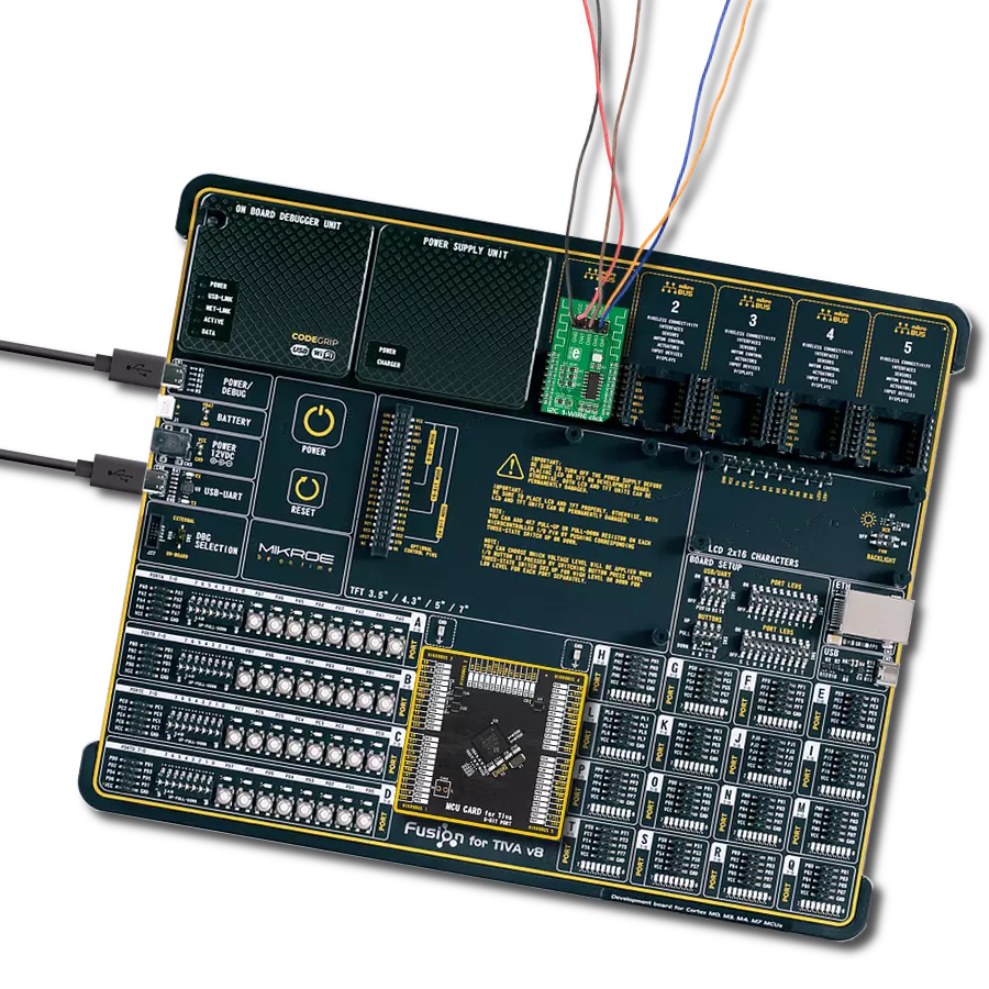
EasyAVR v7
Compiler
NECTO Studio
MCU
ATmega324P
Upgrade your engineering game with the simplicity of 1-Wire and the versatility of I2C today!
A
A
Hardware Overview
How does it work?
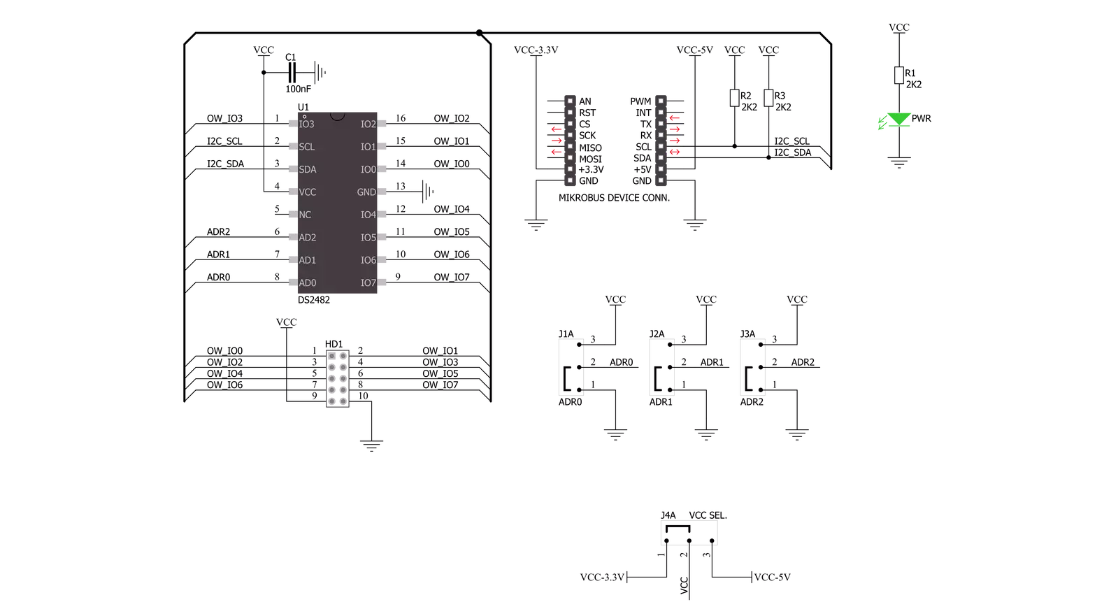
I2C 1-Wire Click is based on the DS2482-800, a self-timed 8-channel 1-Wire master (relative to any attached 1-Wire slave device) from Analog Devices, performing bidirectional conversions between I2C master and 1-Wire slave devices. To optimize 1-Wire waveform generation, the DS2482-800 performs slew-rate control on rising and falling 1-Wire edges. It also has a programmable feature to mask the fast presence pulse edge that some 1-Wire slave devices can generate and programmable strong pull-up features that supports 1-Wire power delivery to 1-Wire devices such as EEPROMs, temperature sensors, and similar devices with momentary high source current modes. The DS2482-800 communicates
with an MCU using the standard I2C 2-Wire interface to read data and configure settings, supporting Fast Mode up to 400kHz. Once supplied with command and data, the I/O controller of the DS2482-800 performs time-critical 1-Wire communication functions such as reset/presence detect cycle, read-byte, write-byte, single-bit R/W and triplet for ROM search without requiring interaction with the host MCU. The host MCU obtains feedback and data (completion of a 1-Wire function, presence pulse, 1-Wire short, search direction taken) through the status and reads data registers. The DS2482-800 has a 7-bit slave address with the first four MSBs fixed to 0011. The address pins, A0, A1, and A2, are programmed
by the user and determine the value of the last three LSBs of the slave address, allowing up to 8 devices to operate on the same bus segment. The value of these address pins can be set by positioning onboard SMD jumpers labeled as I2C ADR to an appropriate position marked as 1 or 0. This Click board™ can operate with both 3.3V and 5V logic voltage levels selected via the PWR SEL jumper. This way, it is allowed for both 3.3V and 5V capable MCUs to use the communication lines properly. However, the Click board™ comes equipped with a library containing easy-to-use functions and an example code that can be used, as a reference, for further development.

Features overview
Development board
EasyAVR v7 is the seventh generation of AVR development boards specially designed for the needs of rapid development of embedded applications. It supports a wide range of 16-bit AVR microcontrollers from Microchip and has a broad set of unique functions, such as a powerful onboard mikroProg programmer and In-Circuit debugger over USB. The development board is well organized and designed so that the end-user has all the necessary elements in one place, such as switches, buttons, indicators, connectors, and others. With four different connectors for each port, EasyAVR v7 allows you to connect accessory boards, sensors, and custom electronics more
efficiently than ever. Each part of the EasyAVR v7 development board contains the components necessary for the most efficient operation of the same board. An integrated mikroProg, a fast USB 2.0 programmer with mikroICD hardware In-Circuit Debugger, offers many valuable programming/debugging options and seamless integration with the Mikroe software environment. Besides it also includes a clean and regulated power supply block for the development board. It can use a wide range of external power sources, including an external 12V power supply, 7-12V AC or 9-15V DC via DC connector/screw terminals, and a power source via the USB Type-B (USB-B)
connector. Communication options such as USB-UART and RS-232 are also included, alongside the well-established mikroBUS™ standard, three display options (7-segment, graphical, and character-based LCD), and several different DIP sockets which cover a wide range of 16-bit AVR MCUs. EasyAVR v7 is an integral part of the Mikroe ecosystem for rapid development. Natively supported by Mikroe software tools, it covers many aspects of prototyping and development thanks to a considerable number of different Click boards™ (over a thousand boards), the number of which is growing every day.

Microcontroller Overview
MCU Card / MCU

Architecture
AVR
MCU Memory (KB)
32
Silicon Vendor
Microchip
Pin count
40
RAM (Bytes)
2048
Used MCU Pins
mikroBUS™ mapper
Take a closer look
Click board™ Schematic
Step by step
Project assembly

Start by selecting your development board and Click board™. Begin with the EasyAVR v7 as your development board.


Track your results in real time
Application Output
1. Application Output - In Debug mode, the 'Application Output' window enables real-time data monitoring, offering direct insight into execution results. Ensure proper data display by configuring the environment correctly using the provided tutorial.

2. UART Terminal - Use the UART Terminal to monitor data transmission via a USB to UART converter, allowing direct communication between the Click board™ and your development system. Configure the baud rate and other serial settings according to your project's requirements to ensure proper functionality. For step-by-step setup instructions, refer to the provided tutorial.

3. Plot Output - The Plot feature offers a powerful way to visualize real-time sensor data, enabling trend analysis, debugging, and comparison of multiple data points. To set it up correctly, follow the provided tutorial, which includes a step-by-step example of using the Plot feature to display Click board™ readings. To use the Plot feature in your code, use the function: plot(*insert_graph_name*, variable_name);. This is a general format, and it is up to the user to replace 'insert_graph_name' with the actual graph name and 'variable_name' with the parameter to be displayed.

Software Support
Library Description
This library contains API for I2C 1-Wire Click driver.
Key functions:
i2conewire_setChannel - Set the channel function..
i2conewire_writeByteOneWire - Generic One Wire writes the byte of data function.
i2conewire_readByteOneWire - Generic One Wire read the byte of data function.
Open Source
Code example
The complete application code and a ready-to-use project are available through the NECTO Studio Package Manager for direct installation in the NECTO Studio. The application code can also be found on the MIKROE GitHub account.
/*!
 * \file
 * \brief I2C1Wire Click example
 *
 * # Description
 * This example showcases how to initialize, confiure and use the I2C 1-Wire Click. The Click
 * is a I2C (host) to 1-Wire interface (slave). In order for the example to work one or more
 * 1-Wire (GPIO) Click modules are required. Gnd goes to gnd, power goes to power and the cha-
 * nnels are there to read data from connected modules.
 *
 * The demo application is composed of two sections :
 *
 * ## Application Init
 * This function initializes and configures the logger and Click modules.
 *
 * ## Application Task
 * This function reads all of the channels on the Click module and displays any data it acqu-
 * ires from them with a 100 millisecond delay.
 *
 *
 * \author MikroE Team
 *
 */
// ------------------------------------------------------------------- INCLUDES

#include "board.h"
#include "log.h"
#include "i2c1wire.h"

// ------------------------------------------------------------------ VARIABLES

static i2c1wire_t i2c1wire;
static log_t logger;

// ------------------------------------------------------ APPLICATION FUNCTIONS

void application_init ( )
{
    log_cfg_t log_cfg;
    i2c1wire_cfg_t cfg;

    /**
     * Logger initialization.
     * Default baud rate: 115200
     * Default log level: LOG_LEVEL_DEBUG
     * @note If USB_UART_RX and USB_UART_TX
     * are defined as HAL_PIN_NC, you will
     * need to define them manually for log to work.
     * See @b LOG_MAP_USB_UART macro definition for detailed explanation.
     */
    LOG_MAP_USB_UART( log_cfg );
    log_init( &logger, &log_cfg );
    log_info( &logger, "---- Application Init ----" );

    //  Click initialization.
    i2c1wire_cfg_setup( &cfg );
    I2C1WIRE_MAP_MIKROBUS( cfg, MIKROBUS_1 );
    i2c1wire_init( &i2c1wire, &cfg );
    Delay_1sec( );
}

void application_task ( )
{
    uint8_t chan_state = 0;
    uint8_t cnt_chan = 0;
    uint8_t cnt_val = 0;
    uint8_t id_code[ 9 ] = { 0 };

    chan_state = 1;

    i2c1wire_soft_reset( &i2c1wire );
    Delay_10ms( );
    i2c1wire_set_config( &i2c1wire, I2C1WIRE_CONFIG_1WS_HIGH |
                                    I2C1WIRE_CONFIG_SPU_HIGH |
                                    I2C1WIRE_CONFIG_APU_LOW );
    Delay_10ms( );

    for ( cnt_chan = 0; cnt_chan < 8; cnt_chan++ )
    {
        i2c1wire_set_channel( &i2c1wire, cnt_chan );
        i2c1wire_one_wire_reset( &i2c1wire );
        Delay_10ms( );

        i2c1wire_write_byte_one_wire( &i2c1wire, I2C1WIRE_WIRE_COMMAND_READ_ROM );
        Delay_10ms();

        for ( cnt_val = 8; cnt_val > 0; cnt_val-- )
        {
            id_code[ cnt_val ] = i2c1wire_read_byte_one_wire( &i2c1wire );

            if ( id_code[ cnt_val ] == I2C1WIRE_WIRE_RESULT_OK )
            {
                log_printf( &logger, "\r\n Channel %d : No device on the channel\r\n", ( uint16_t ) cnt_chan );
                Delay_100ms( );
                break;
            }
            else if ( chan_state )
            {
                log_printf( &logger, " Channel %d : ID = 0x", ( uint16_t ) cnt_chan );
                chan_state = 0;
            }

            log_printf( &logger, "%d", ( uint16_t ) id_code[ cnt_val ] );
            Delay_10ms( );
        }

        log_printf( &logger, "\r\n---------------------------------------\r\n" );
    }

    log_printf( &logger, "***\r\n" );
}

int main ( void )
{
    /* Do not remove this line or clock might not be set correctly. */
    #ifdef PREINIT_SUPPORTED
    preinit();
    #endif

    application_init( );

    for ( ; ; )
    {
        application_task( );
    }

    return 0;
}

// ------------------------------------------------------------------------ END