Empower your electronics with the power of optical isolation based on the LTV-817S and ATmega324P
Guardian of signals: OptoSentry for total isolation!

Published Sep 21, 2023
Click board™
OPTO 4 Click
Dev. board
EasyAVR v7
Compiler
NECTO Studio
MCU
ATmega324P
Achieve cleaner and more reliable signal transmission by isolating your circuits from electrical noise and disturbances
A
A
Hardware Overview
How does it work?
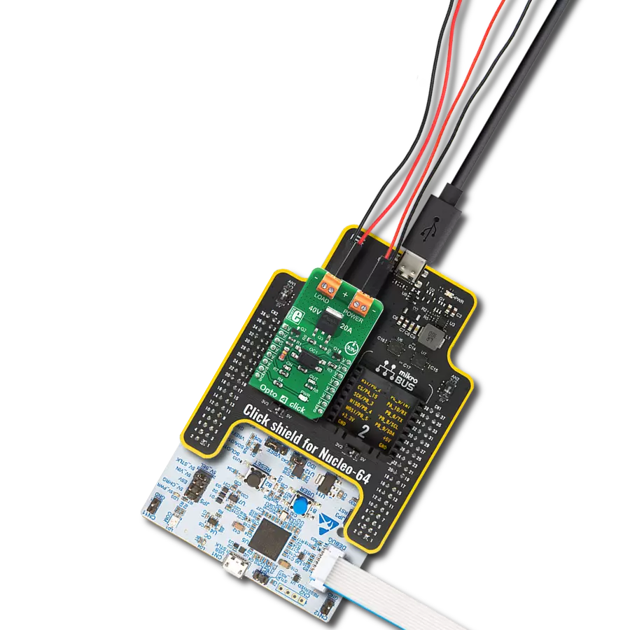
Opto 4 Click is based on the LTV-817S, an optocoupler with a high isolation voltage from ON Semiconductor. This is a single-channel optocoupler which uses the low current provided by the output pin of the microcontroller (MCU) to activate its output stage. Besides an internal biasing LED, the MCU drives an additional external yellow LED, which signalizes that the MCU output is at a HIGH logic level. This led is labeled as ON, and it is used to indicate the state of the optocoupler output stage (conductive or non-conductive). The host MCU uses the CS pin of the mikroBUS™ to drive the input stage of the LTV-817S optocoupler. The working principle of an optocoupler is quite simple: A photo-emitting element - usually an IR LED - is integrated on a die along with the photosensitive element, usually a photosensitive transistor. The LED and the photosensitive transistor are isolated galvanically, but not optically: when the internal LED is powered, it emits light, which biases the base of the photosensitive transistor at the output stage, allowing the current to flow through it. In practice, an optocoupler may be equipped with additional elements such as Schmitt triggers, photo-sensitive Darlington pairs, various configurations of MOSFETs, and more. The output stage of the
optocoupler is used to drive the gate terminal of the FDD10AN06A0, an external power MOSFET, manufactured using the PowerTrench® technology, by ON Semiconductor. This MOSFET allows much more current to flow through the connected load, due to its extremely low ON resistance of about 10 mΩ, typically (10V). This MOSFET is designed to be used in switching circuits and for DC/DC converters, providing a high efficiency for these applications. As such, it has a very low capacitance on its gate terminal, allowing it to be driven with reasonably high-frequency PWM signals. The output stage of the LTV-817S optocoupler is connected to the VIN terminal of the external power supply connector, labeled as POWER. When the output stage of the optocoupler is closed (CS pin of the mikroBUS™ is at a HIGH logic level), it will connect the gate of the power MOSFET to the VIN voltage, thus enabling the power MOSFET. When the output stage of the optocoupler is opened (CS pin is at a LOW logic level), the gate of the MOSFET will be pulled down to the GND, by a 10K resistor, disabling the MOSFET. While enabled, the power MOSFET will be able to conduct the current through an external load, connected to the LOAD terminal. The output stage of the optocoupler also
has a green LED indicator labeled as OUT, which indicates that there is a valid voltage level across the POWER terminal. An undervoltage circuit on the VIN terminal prevents the voltage of the external power supply to drop under 10V. Ideally, the power supply voltage should stay above 12V. It is important for the voltage of the power supply to stay above 10V, since in that case, the ON resistance of the MOSFET is about 10 mΩ, ensuring that no significant heat dissipation will occur as a result of high current through the load. As the voltage of the externally connected power supply drops, it may cause the ON resistance of the power MOSFET to rise enough even before activating the undervoltage circuit (depending on the current through the load), resulting in its damaging. Therefore, the voltage of the external power supply must stay above 10V for this Click board™ to work reliably. The undervoltage protection feature can be useful to switch off the load in the case when the short-circuit condition occurs: the voltage of the power supply during short circuit event may drop, resulting the undervoltage circuit to be activated. However, if a reasonably strong power supply is used, the short-circuit current may be enough to destroy the power MOSFET or the input terminals.


Features overview
Development board
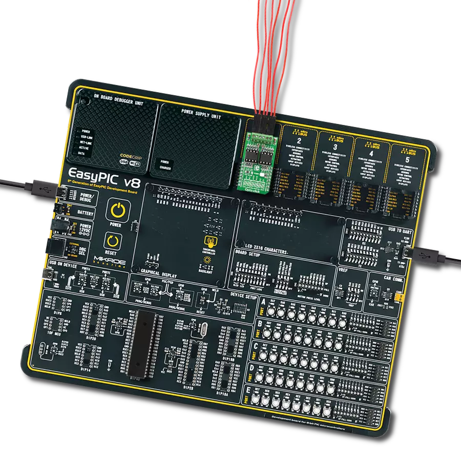
EasyAVR v7 is the seventh generation of AVR development boards specially designed for the needs of rapid development of embedded applications. It supports a wide range of 16-bit AVR microcontrollers from Microchip and has a broad set of unique functions, such as a powerful onboard mikroProg programmer and In-Circuit debugger over USB. The development board is well organized and designed so that the end-user has all the necessary elements in one place, such as switches, buttons, indicators, connectors, and others. With four different connectors for each port, EasyAVR v7 allows you to connect accessory boards, sensors, and custom electronics more
efficiently than ever. Each part of the EasyAVR v7 development board contains the components necessary for the most efficient operation of the same board. An integrated mikroProg, a fast USB 2.0 programmer with mikroICD hardware In-Circuit Debugger, offers many valuable programming/debugging options and seamless integration with the Mikroe software environment. Besides it also includes a clean and regulated power supply block for the development board. It can use a wide range of external power sources, including an external 12V power supply, 7-12V AC or 9-15V DC via DC connector/screw terminals, and a power source via the USB Type-B (USB-B)
connector. Communication options such as USB-UART and RS-232 are also included, alongside the well-established mikroBUS™ standard, three display options (7-segment, graphical, and character-based LCD), and several different DIP sockets which cover a wide range of 16-bit AVR MCUs. EasyAVR v7 is an integral part of the Mikroe ecosystem for rapid development. Natively supported by Mikroe software tools, it covers many aspects of prototyping and development thanks to a considerable number of different Click boards™ (over a thousand boards), the number of which is growing every day.

Microcontroller Overview
MCU Card / MCU

Architecture
AVR
MCU Memory (KB)
32
Silicon Vendor
Microchip
Pin count
40
RAM (Bytes)
2048
Used MCU Pins
mikroBUS™ mapper
Take a closer look
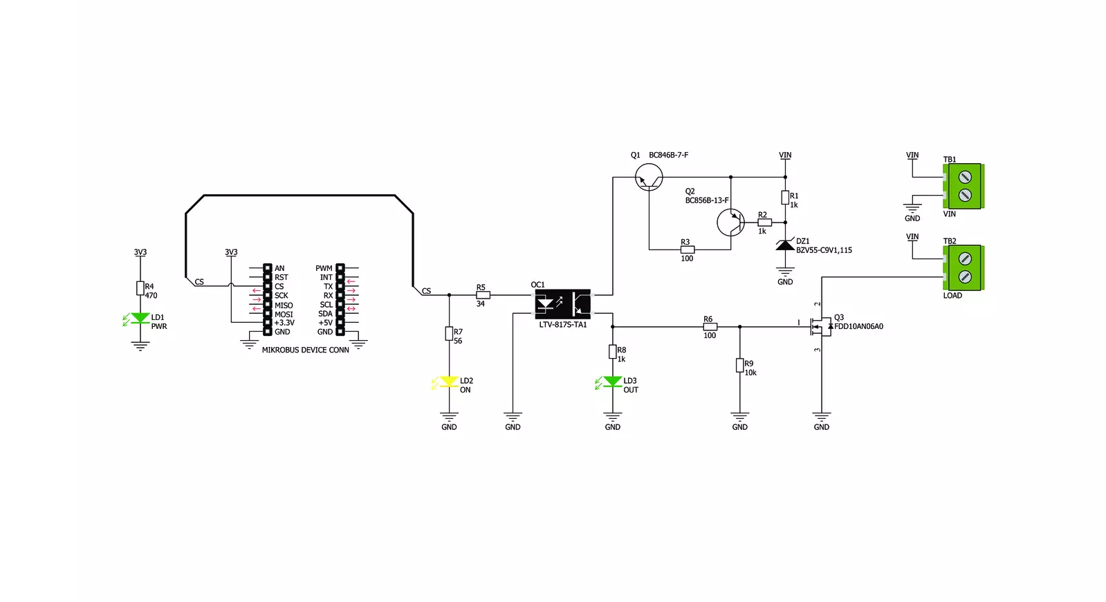
Click board™ Schematic
Step by step
Project assembly

Start by selecting your development board and Click board™. Begin with the EasyAVR v7 as your development board.


Software Support
Library Description
This library contains API for OPTO 4 Click driver.
Key functions:
opto4_output_enable- Function for output enable or disable
Open Source
Code example
The complete application code and a ready-to-use project are available through the NECTO Studio Package Manager for direct installation in the NECTO Studio. The application code can also be found on the MIKROE GitHub account.
/*!
 * \file
 * \brief OPTO 4 Click example
 *
 * # Description
 * This Click sets power on switch enabled and disabled.
 *
 * The demo application is composed of two sections :
 *
 * ## Application Init
 * Initialization driver init.
 *
 * ## Application Task
 * The Output voltage enable and disable every 3 sec.
 *
 * \author MikroE Team
 *
 */
// ------------------------------------------------------------------- INCLUDES

#include "board.h"
#include "log.h"
#include "opto4.h"

// ------------------------------------------------------------------ VARIABLES

static opto4_t opto4;
static log_t logger;

// ------------------------------------------------------ APPLICATION FUNCTIONS

void application_init ( void )
{
    log_cfg_t log_cfg;
    opto4_cfg_t cfg;

    /**
     * Logger initialization.
     * Default baud rate: 115200
     * Default log level: LOG_LEVEL_DEBUG
     * @note If USB_UART_RX and USB_UART_TX
     * are defined as HAL_PIN_NC, you will
     * need to define them manually for log to work.
     * See @b LOG_MAP_USB_UART macro definition for detailed explanation.
     */
    LOG_MAP_USB_UART( log_cfg );
    log_init( &logger, &log_cfg );
    log_info(&logger, "---- Application Init ----");

    //  Click initialization.

    opto4_cfg_setup( &cfg );
    OPTO4_MAP_MIKROBUS( cfg, MIKROBUS_1 );
    opto4_init( &opto4, &cfg );
}

void application_task ( )
{
    opto4_output_enable( &opto4, OPTO4_OUTPUT_ENABLE );
    Delay_ms ( 1000 );
    Delay_ms ( 1000 );
    Delay_ms ( 1000 );
    opto4_output_enable( &opto4, OPTO4_OUTPUT_DISABLE );
    Delay_ms ( 1000 );
    Delay_ms ( 1000 );
    Delay_ms ( 1000 );
}

int main ( void )
{
    /* Do not remove this line or clock might not be set correctly. */
    #ifdef PREINIT_SUPPORTED
    preinit();
    #endif

    application_init( );

    for ( ; ; )
    {
        application_task( );
    }

    return 0;
}


// ------------------------------------------------------------------------ END