Optimize your systems, enhance safety, and achieve reliability with MAX17608 and ATmega1284
Empowering innovation, one Amp at a time

Published Oct 12, 2023
Click board™
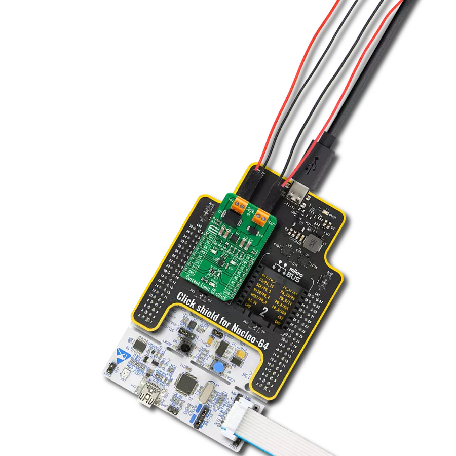
Current Limit 6 Click
Dev. board
EasyAVR v7
Compiler
NECTO Studio
MCU
ATmega1284
Our current limiting solution is engineered to revolutionize safety and efficiency, offering precise control over current to ensure optimal performance while safeguarding your systems against overloads
A
A
Hardware Overview
How does it work?
Current Limit 6 Click is based on the MAX17608, a current-limiting device with an adjustable overvoltage and overcurrent protection feature from Analog Devices. The MAX17608 offers flexible protection boundaries for systems against input voltage ranging from 4.5V to 60V and limits the output load current to a programmed level (up to 1A). The devices also feature two internal MOSFETs connected in series, with a low cumulative RON of 260mΩ typical. Input undervoltage protection can be programmed between 4.5V and 59V, while the overvoltage protection can be independently programmed between 5.5V and 60V (default Click board™ configuration is 4.5V for UVLO and 14V for OVLO). Additionally, the MAX17608 has an internal default undervoltage lockout set at 4V typical. The current-limit switch is virtually ubiquitous in system control and provides a safe means for regulating the current delivered to a load circuit. It increases the load current to a programmed limit but no higher. Typically, the current limit is a
function of the voltage across an external resistor, and this voltage serves as the reference for an internal current-limiting amplifier. Replacing the resistor with a digital potentiometer allows you to program the current limit as performed on this Click board™. For this purpose, the digital potentiometer MAX5401 from Analog Devices, which communicates with the MCU via a 3-wire SPI serial interface, is used to set the resistance on the MAX17608 SETI pin, adjusting the current limit for the switch between 0.1A to 1 A. This current limiter offers several operational modes, selectable through a populated jumper labeled as R11 connected to the CLMD pin of the MAX17608. In a default configuration, this pin is connected to the ground, representing the Continuous mode of operation. When R11 is replaced with a 150kΩ resistor, this Click board™ is in the Latch-off mode, and when the user leaves this pin unconnected, Autoretry mode of operation is activated. More information on the operational modes
can be found in the attached datasheet. Current Limit 6 Click can be turned on, or off through the EN pin routed to the PWM pin of the mikroBUS™ socket, hence offering a switch operation to turn ON/OFF power delivery to the connected load. It also provides communication signals routed to the INT and AN pins of the mikroBUS™ socket, alongside its LED indicators, labeled ER1 and ER2, to indicate different operational and fault signals, such as FLAG and UVOV signals. Besides, the MAX17608 also offers internal thermal shutdown protection against excessive power dissipation. This Click board™ can operate with either 3.3V or 5V logic voltage levels selected via the VCC SEL jumper. This way, both 3.3V and 5V capable MCUs can use the communication lines properly. Also, this Click board™ comes equipped with a library containing easy-to-use functions and an example code that can be used as a reference for further development.

Features overview
Development board
EasyAVR v7 is the seventh generation of AVR development boards specially designed for the needs of rapid development of embedded applications. It supports a wide range of 16-bit AVR microcontrollers from Microchip and has a broad set of unique functions, such as a powerful onboard mikroProg programmer and In-Circuit debugger over USB. The development board is well organized and designed so that the end-user has all the necessary elements in one place, such as switches, buttons, indicators, connectors, and others. With four different connectors for each port, EasyAVR v7 allows you to connect accessory boards, sensors, and custom electronics more
efficiently than ever. Each part of the EasyAVR v7 development board contains the components necessary for the most efficient operation of the same board. An integrated mikroProg, a fast USB 2.0 programmer with mikroICD hardware In-Circuit Debugger, offers many valuable programming/debugging options and seamless integration with the Mikroe software environment. Besides it also includes a clean and regulated power supply block for the development board. It can use a wide range of external power sources, including an external 12V power supply, 7-12V AC or 9-15V DC via DC connector/screw terminals, and a power source via the USB Type-B (USB-B)
connector. Communication options such as USB-UART and RS-232 are also included, alongside the well-established mikroBUS™ standard, three display options (7-segment, graphical, and character-based LCD), and several different DIP sockets which cover a wide range of 16-bit AVR MCUs. EasyAVR v7 is an integral part of the Mikroe ecosystem for rapid development. Natively supported by Mikroe software tools, it covers many aspects of prototyping and development thanks to a considerable number of different Click boards™ (over a thousand boards), the number of which is growing every day.

Microcontroller Overview
MCU Card / MCU

Architecture
AVR
MCU Memory (KB)
128
Silicon Vendor
Microchip
Pin count
40
RAM (Bytes)
16384
Used MCU Pins
mikroBUS™ mapper
Take a closer look
Click board™ Schematic

Step by step
Project assembly

Start by selecting your development board and Click board™. Begin with the EasyAVR v7 as your development board.


Track your results in real time
Application Output
1. Application Output - In Debug mode, the 'Application Output' window enables real-time data monitoring, offering direct insight into execution results. Ensure proper data display by configuring the environment correctly using the provided tutorial.

2. UART Terminal - Use the UART Terminal to monitor data transmission via a USB to UART converter, allowing direct communication between the Click board™ and your development system. Configure the baud rate and other serial settings according to your project's requirements to ensure proper functionality. For step-by-step setup instructions, refer to the provided tutorial.

3. Plot Output - The Plot feature offers a powerful way to visualize real-time sensor data, enabling trend analysis, debugging, and comparison of multiple data points. To set it up correctly, follow the provided tutorial, which includes a step-by-step example of using the Plot feature to display Click board™ readings. To use the Plot feature in your code, use the function: plot(*insert_graph_name*, variable_name);. This is a general format, and it is up to the user to replace 'insert_graph_name' with the actual graph name and 'variable_name' with the parameter to be displayed.

Software Support
Library Description
This library contains API for Current Limit 6 Click driver.
Key functions:
currentlimit6_set_current_limit- Current Limit 6 set current limit functioncurrentlimit6_power_mode- Current Limit 6 power mode functioncurrentlimit6_check_limit_exceeded- Current Limit 6 check limit exceeded function
Open Source
Code example
The complete application code and a ready-to-use project are available through the NECTO Studio Package Manager for direct installation in the NECTO Studio. The application code can also be found on the MIKROE GitHub account.
/*!
* @file main.c
* @brief CurrentLimit6 Click example
*
* # Description
* This library contains API for the Current Limit 6 Click driver.
* This driver provides the functions to set the current limiting conditions
* in order to provide the threshold of the fault conditions.
*
* The demo application is composed of two sections :
*
* ## Application Init
* Initialization of SPI module and log UART.
* After driver initialization, default settings turn on the device.
*
* ## Application Task
* This example demonstrates the use of the Current Limit 6 Click board™.
* Reading user's input from Usart Terminal and using it as an index
* for an array of pre-calculated values that define the current limit level.
* Results are being sent to the Usart Terminal, where you can track their changes.
*
* ## Additional Function
* - static void display_selection ( void )
*
* @author Nenad Filipovic
*
*/
#include "board.h"
#include "log.h"
#include "currentlimit6.h"
static currentlimit6_t currentlimit6;
static log_t logger;
const float limit_value[ 9 ] = { 0.100, 0.200, 0.300, 0.400, 0.500, 0.600, 0.700, 0.800, 0.999 };
static void display_selection ( void )
{
log_printf( &logger, " To select current limit \r\n" );
log_printf( &logger, " Send one of the numbers: \r\n" );
log_printf( &logger, "- - - - - - - - - - - - - \r\n" );
log_printf( &logger, " '1' - Limited to 100 mA \r\n" );
log_printf( &logger, " '2' - Limited to 200 mA \r\n" );
log_printf( &logger, " '3' - Limited to 300 mA \r\n" );
log_printf( &logger, " '4' - Limited to 400 mA \r\n" );
log_printf( &logger, " '5' - Limited to 500 mA \r\n" );
log_printf( &logger, " '6' - Limited to 600 mA \r\n" );
log_printf( &logger, " '7' - Limited to 700 mA \r\n" );
log_printf( &logger, " '8' - Limited to 800 mA \r\n" );
log_printf( &logger, " '9' - Limited to 999 mA \r\n" );
log_printf( &logger, "--------------------------\r\n" );
}
void application_init ( void )
{
log_cfg_t log_cfg; /**< Logger config object. */
currentlimit6_cfg_t currentlimit6_cfg; /**< Click config object. */
/**
* Logger initialization.
* Default baud rate: 115200
* Default log level: LOG_LEVEL_DEBUG
* @note If USB_UART_RX and USB_UART_TX
* are defined as HAL_PIN_NC, you will
* need to define them manually for log to work.
* See @b LOG_MAP_USB_UART macro definition for detailed explanation.
*/
LOG_MAP_USB_UART( log_cfg );
log_init( &logger, &log_cfg );
log_info( &logger, " Application Init " );
// Click initialization.
currentlimit6_cfg_setup( ¤tlimit6_cfg );
CURRENTLIMIT6_MAP_MIKROBUS( currentlimit6_cfg, MIKROBUS_1 );
if ( SPI_MASTER_ERROR == currentlimit6_init( ¤tlimit6, ¤tlimit6_cfg ) )
{
log_error( &logger, " Communication init." );
for ( ; ; );
}
if ( CURRENTLIMIT6_ERROR == currentlimit6_default_cfg ( ¤tlimit6 ) )
{
log_error( &logger, " Default configuration." );
for ( ; ; );
}
log_info( &logger, " Application Task " );
log_printf( &logger, "-------------------------\r\n" );
log_printf( &logger, " Current Limit 6 Click \r\n" );
log_printf( &logger, "-------------------------\r\n" );
log_printf( &logger, "- - - - - - - - - - - - -\r\n" );
Delay_ms ( 100 );
display_selection( );
Delay_ms ( 100 );
}
void application_task ( void )
{
static char index;
if ( log_read( &logger, &index, 1 ) != CURRENTLIMIT6_ERROR )
{
if ( ( index >= '1' ) && ( index <= '9' ) )
{
currentlimit6_set_current_limit ( ¤tlimit6, limit_value[ index - 49 ] );
log_printf( &logger, " >>> Selected mode %d \r\n", index - 48 );
log_printf( &logger, "- - - - - - - - - - - - -\r\n" );
log_printf( &logger, " Current limit is %.3f A \r\n", limit_value[ index - 49 ] );
log_printf( &logger, "--------------------------\r\n" );
Delay_ms ( 100 );
}
else
{
log_printf( &logger, " Data not in range! \r\n" );
log_printf( &logger, "--------------------------\r\n" );
display_selection( );
Delay_ms ( 100 );
}
}
}
int main ( void )
{
/* Do not remove this line or clock might not be set correctly. */
#ifdef PREINIT_SUPPORTED
preinit();
#endif
application_init( );
for ( ; ; )
{
application_task( );
}
return 0;
}
// ------------------------------------------------------------------------ END