Stay safe from harmful NO2 with MiCS-2714 and ATmega644
NO2 detect, health protect: Your solution for cleaner, safer air

Published Aug 29, 2023
Click board™
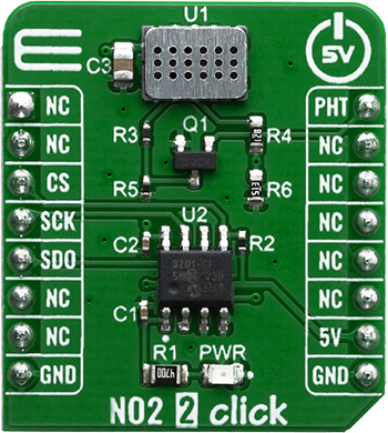
NO2 2 Click
Dev. board
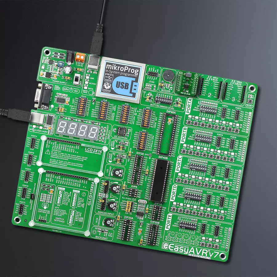
EasyAVR v7
Compiler
NECTO Studio
MCU
ATmega644
Join the fight against NO2 pollution with your engineering skills.
A
A
Hardware Overview
How does it work?
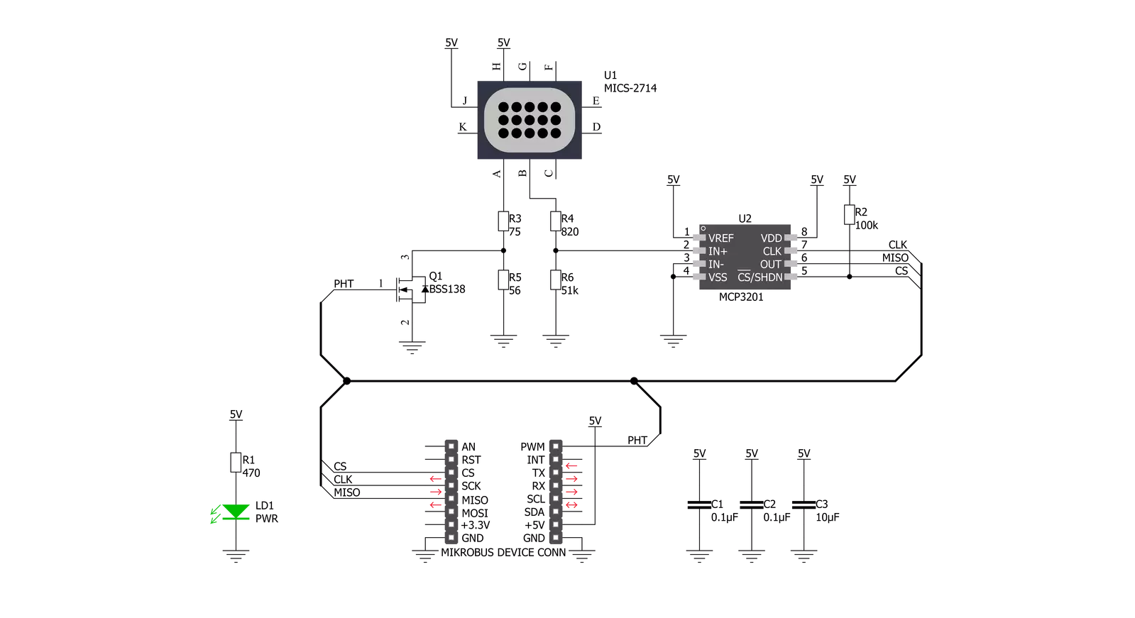
NO2 2 Click is based on the MiCS-2714 sensor, a compact MOS sensor from SGX Sensortech. This sensor comprises a micromachined metal oxide semiconductor diaphragm with an integrated heating resistor. The resistor produces heat, which catalyzes the reaction, affecting the electrical resistance of the oxide layer itself. The temperature of the heater is quite high: it ranges from 350 °C to 550 °C. After the initial preheating period, the sensor can detect gas changes in intervals below two seconds. The resistance of the MiCS-2714 sensor does not change linearly with the gas concentration, so a proper calibration must be performed before using it for absolute gas concentration measurement applications. The impedance changes the most when used with low
gas concentrations. As the atmosphere gets saturated with gas, the impedance changes slowly. The MiCS-2714 sensor is a simple device: it has only four connections. Two pins are the connections of the internal heating element, while the other two are the MOS sensor connections. The application is reduced to calculating a proper resistor for the voltage divider. The middle tap between the sensor (as a resistor) and the fixed resistance provides an output voltage. It directly depends on the sensor's resistance, allowing it to be used as the input into the MCP3201, a low-power 12-bit A/D converter with an I2C interface, from Microchip. This ADC allows the output voltage to be translated into digital information, accessed over the I2C pins on the mikroBUS™
socket. By using the power supply voltage as the voltage reference for the conversion, this ADC further reduces the complexity of the design, still offering a good conversion quality, thanks to its low noise input. Due to the sensor's inert nature, this ADC is more than fast enough, although it can provide up to 22.3ksps when operated in the I2C Fast mode. This Click board™ can be operated only with a 5V logic voltage level. The board must perform appropriate logic voltage level conversion before using MCUs with different logic levels. Also, it comes equipped with a library containing functions and an example code that can be used as a reference for further development.


Features overview
Development board
EasyAVR v7 is the seventh generation of AVR development boards specially designed for the needs of rapid development of embedded applications. It supports a wide range of 16-bit AVR microcontrollers from Microchip and has a broad set of unique functions, such as a powerful onboard mikroProg programmer and In-Circuit debugger over USB. The development board is well organized and designed so that the end-user has all the necessary elements in one place, such as switches, buttons, indicators, connectors, and others. With four different connectors for each port, EasyAVR v7 allows you to connect accessory boards, sensors, and custom electronics more
efficiently than ever. Each part of the EasyAVR v7 development board contains the components necessary for the most efficient operation of the same board. An integrated mikroProg, a fast USB 2.0 programmer with mikroICD hardware In-Circuit Debugger, offers many valuable programming/debugging options and seamless integration with the Mikroe software environment. Besides it also includes a clean and regulated power supply block for the development board. It can use a wide range of external power sources, including an external 12V power supply, 7-12V AC or 9-15V DC via DC connector/screw terminals, and a power source via the USB Type-B (USB-B)
connector. Communication options such as USB-UART and RS-232 are also included, alongside the well-established mikroBUS™ standard, three display options (7-segment, graphical, and character-based LCD), and several different DIP sockets which cover a wide range of 16-bit AVR MCUs. EasyAVR v7 is an integral part of the Mikroe ecosystem for rapid development. Natively supported by Mikroe software tools, it covers many aspects of prototyping and development thanks to a considerable number of different Click boards™ (over a thousand boards), the number of which is growing every day.

Microcontroller Overview
MCU Card / MCU

Architecture
AVR
MCU Memory (KB)
64
Silicon Vendor
Microchip
Pin count
40
RAM (Bytes)
4096
Used MCU Pins
mikroBUS™ mapper
Take a closer look
Click board™ Schematic
Step by step
Project assembly

Start by selecting your development board and Click board™. Begin with the EasyAVR v7 as your development board.


Track your results in real time
Application Output
1. Application Output - In Debug mode, the 'Application Output' window enables real-time data monitoring, offering direct insight into execution results. Ensure proper data display by configuring the environment correctly using the provided tutorial.

2. UART Terminal - Use the UART Terminal to monitor data transmission via a USB to UART converter, allowing direct communication between the Click board™ and your development system. Configure the baud rate and other serial settings according to your project's requirements to ensure proper functionality. For step-by-step setup instructions, refer to the provided tutorial.

3. Plot Output - The Plot feature offers a powerful way to visualize real-time sensor data, enabling trend analysis, debugging, and comparison of multiple data points. To set it up correctly, follow the provided tutorial, which includes a step-by-step example of using the Plot feature to display Click board™ readings. To use the Plot feature in your code, use the function: plot(*insert_graph_name*, variable_name);. This is a general format, and it is up to the user to replace 'insert_graph_name' with the actual graph name and 'variable_name' with the parameter to be displayed.

Software Support
Library Description
This library contains API for NO2 2 Click driver.
Key functions:
no22_read_data- Function for reading ADC datano22_get_ppb- Function for reading ppb datano22_set_pht_state- Function for setting pht pin
Open Source
Code example
The complete application code and a ready-to-use project are available through the NECTO Studio Package Manager for direct installation in the NECTO Studio. The application code can also be found on the MIKROE GitHub account.
/*!
 * \file
 * \brief NO22 Click example
 *
 * # Description
 * Measure the level of NO2
 *
 * The demo application is composed of two sections :
 *
 * ## Application Init
 * Driver init
 *
 * ## Application Task
 * Measures in span of 1 seconc ppb of NO2
 *
 * \author MikroE Team
 *
 */
// ------------------------------------------------------------------- INCLUDES

#include "board.h"
#include "log.h"
#include "no22.h"

// ------------------------------------------------------------------ VARIABLES

static no22_t no22;
static log_t logger;

// ------------------------------------------------------ APPLICATION FUNCTIONS

void application_init ( void )
{
    log_cfg_t log_cfg;
    no22_cfg_t cfg;
    uint8_t error_data;

    /**
     * Logger initialization.
     * Default baud rate: 115200
     * Default log level: LOG_LEVEL_DEBUG
     * @note If USB_UART_RX and USB_UART_TX
     * are defined as HAL_PIN_NC, you will
     * need to define them manually for log to work.
     * See @b LOG_MAP_USB_UART macro definition for detailed explanation.
     */
    LOG_MAP_USB_UART( log_cfg );
    log_init( &logger, &log_cfg );
    log_info( &logger, "---- Application Init ----" );

    //  Click initialization.

    no22_cfg_setup( &cfg );
    NO22_MAP_MIKROBUS( cfg, MIKROBUS_1 );
    no22_init( &no22, &cfg );

    error_data = no22_set_pht_state( &no22, NO22_PIN_STATE_LOW );

    if ( error_data == NO22_DEVICE_ERROR )
    {
        log_printf( &logger, "Device error \r\n" );
        for ( ; ; );
    }

    log_printf( &logger, "***** App init ***** \r\n" );
}

void application_task ( )
{
    uint16_t temp_data_read;
    float data_ppb;

    temp_data_read = no22_read_data( &no22 );
    log_printf( &logger, "ADC: %d \n\r", temp_data_read );

    data_ppb = no22_get_ppb( &no22 );
    log_printf( &logger, "PPB: %f \r\n", data_ppb );

    log_printf( &logger, "___________________________\r\n" );

    Delay_ms ( 1000 );
}

int main ( void )
{
    /* Do not remove this line or clock might not be set correctly. */
    #ifdef PREINIT_SUPPORTED
    preinit();
    #endif

    application_init( );

    for ( ; ; )
    {
        application_task( );
    }

    return 0;
}


// ------------------------------------------------------------------------ END


