Crafting seamless Bluetooth audio experiences with RN52 and ATmega324P
Tune in, cable out

Published Jul 27, 2023
Click board™
BT Audio Click
Dev. board
EasyAVR v7
Compiler
NECTO Studio
MCU
ATmega324P
Our cutting-edge solution enables seamless audio streaming over Bluetooth, allowing you to untether from cables and enjoy the freedom of wireless connectivity. Immerse yourself in a world of uninterrupted music and dynamic audio experiences.
A
A
Hardware Overview
How does it work?
BT Audio Click is based on the RN52, a Bluetooth audio module from Microchip. This Bluetooth 3.0 module integrates an RF radio and a baseband controller making it a complete Bluetooth subsystem. It supports A2DP, AVRCHP, HFP, SPP, and iAP profiles in a Bluetooth slave role and A2DP, AVRCP, and HFP in a Bluetooth master role. For implementing the iAP profile, the host MCU uses the RN52 as a data pipe to transfer the data over Bluetooth. This wireless profile advertising is discoverable by iOS devices. The RN52 module has an integrated amplifier for driving 16 ohms speakers over the onboard 3.5mm audio connector. The TPA6112, a stereo audio power amplifier from Texas Instruments, features differential inputs, pop reduction circuitry, thermal and short-circuit protection, and more. Differential architecture in the analog path results in a low noise sensitivity and good power supply rejection while effectively doubling the signal amplitude. In addition to the audio output, this Click board™ is equipped with a 3.5mm audio connector for connecting a microphone. An analog and digital programmable gain stage can be optimized for different microphones. The supported audio resolution is 24-bit with a maximum channel size
of 32-bit. The module's analog-to-digital converter (ADC) supports sample rates of 8KHz, 32KHz, 44.1KHz, and 48KHz. The same sample rates are supported by two DACs, one for each speaker. The host MCU can configure both the sample rate and audio resolution. The RN52 module uses a printed antenna for Bluetooth wireless communication. BT Audio click has a 10m range in open space. The range is shorter indoors but still enough to cover a few rooms. The DSP, or digital signal processor, makes this module special because it can stream audio – it converts and compresses the radio waves sent from your phone or computer into digital data, then sends it to your speakers or headphones. The module supports aptX, an audio codec for high-quality stereo audio streaming over Bluetooth. So, the sound quality is not something you must compromise on, as aptX encodes a CD-quality (16-bit / 44.1kHz) audio stream. HSP/HFP stands for Hands-Free Profile and Headset Profile for an audio connection between Bluetooth on your phone and the headset. BT Audio Click uses a UART interface to communicate with the host MCU, with commonly used UART RX and TX, supporting baud rates of 9600 up to 115200. The baud rate is set to 9600 by default via the
pull-down resistor and can be set to 115200 with a logic HIGH on the BAUD pin. The RN52's UART is set to Command mode by pulling the CMD pin to a logic HIGH; otherwise, the UART enters the Data mode. While in Command mode, the user can configure the module with the ASCII commands. In Data mode, the module is processing the data. There are two additional pins, RST and FRS, representing the general-purpose reset and factory reset functions that allow users to reset the module to factory defaults. The PWR pin power up the module with the HIGH logic state. There are two LEDs on this Click board™, red and blue. While both are flashing, the BT Audio Click is discoverable. If red is only flashing, the module is connected; if blue is only flashing, the module is connectable. This Click board™ can only be operated with a 3.3V logic voltage level. The board must perform appropriate logic voltage level conversion before using MCUs with different logic levels. However, the Click board™ comes equipped with a library containing functions and an example code that can be used, as a reference, for further development.

Features overview
Development board
EasyAVR v7 is the seventh generation of AVR development boards specially designed for the needs of rapid development of embedded applications. It supports a wide range of 16-bit AVR microcontrollers from Microchip and has a broad set of unique functions, such as a powerful onboard mikroProg programmer and In-Circuit debugger over USB. The development board is well organized and designed so that the end-user has all the necessary elements in one place, such as switches, buttons, indicators, connectors, and others. With four different connectors for each port, EasyAVR v7 allows you to connect accessory boards, sensors, and custom electronics more
efficiently than ever. Each part of the EasyAVR v7 development board contains the components necessary for the most efficient operation of the same board. An integrated mikroProg, a fast USB 2.0 programmer with mikroICD hardware In-Circuit Debugger, offers many valuable programming/debugging options and seamless integration with the Mikroe software environment. Besides it also includes a clean and regulated power supply block for the development board. It can use a wide range of external power sources, including an external 12V power supply, 7-12V AC or 9-15V DC via DC connector/screw terminals, and a power source via the USB Type-B (USB-B)
connector. Communication options such as USB-UART and RS-232 are also included, alongside the well-established mikroBUS™ standard, three display options (7-segment, graphical, and character-based LCD), and several different DIP sockets which cover a wide range of 16-bit AVR MCUs. EasyAVR v7 is an integral part of the Mikroe ecosystem for rapid development. Natively supported by Mikroe software tools, it covers many aspects of prototyping and development thanks to a considerable number of different Click boards™ (over a thousand boards), the number of which is growing every day.

Microcontroller Overview
MCU Card / MCU

Architecture
AVR
MCU Memory (KB)
32
Silicon Vendor
Microchip
Pin count
40
RAM (Bytes)
2048
You complete me!
Accessories
These standard small stereo earphones offer a high-quality listening experience with their top-notch stereo cable and connector. Designed for universal compatibility, they effortlessly connect to all MIKROE mikromedia and multimedia boards, making them an ideal choice for your electronic projects. With a rated power of 100mW, the earphones provide crisp audio across a broad frequency range from 20Hz to 20kHz. They boast a sensitivity of 100 ± 5dB and an impedance of 32Ω ± 15%, ensuring optimal sound quality. The Φ15mm speaker delivers clear and immersive audio. Cost-effective and versatile, these earphones are perfect for testing your prototype devices, offering an affordable and reliable audio solution to complement your projects.

Used MCU Pins
mikroBUS™ mapper
Take a closer look
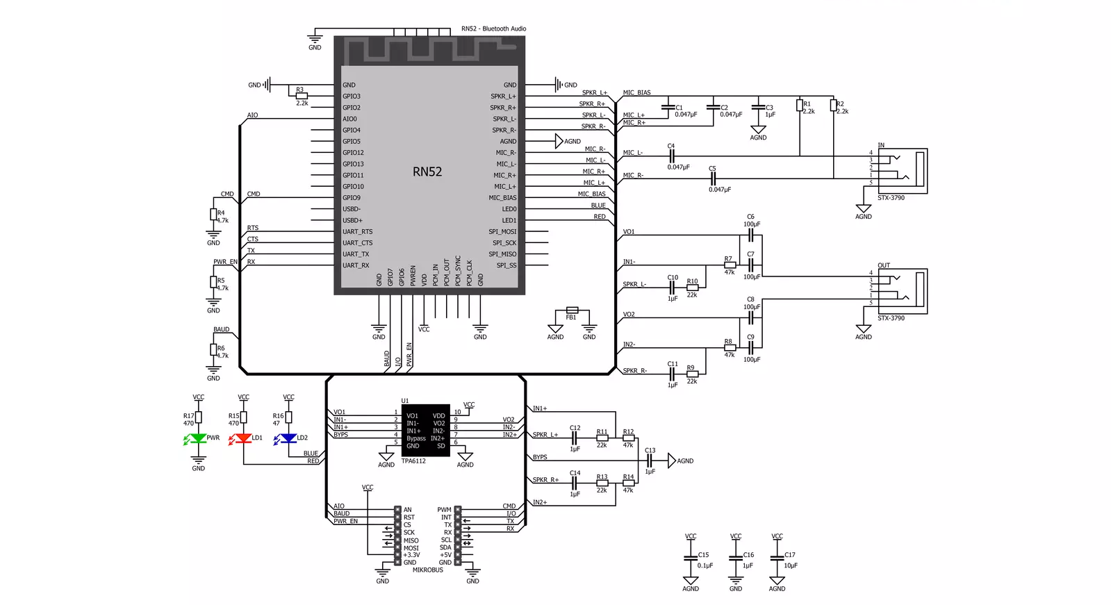
Click board™ Schematic
Step by step
Project assembly

Start by selecting your development board and Click board™. Begin with the EasyAVR v7 as your development board.


Software Support
Library Description
This library contains API for BT Audio Click driver.
Key functions:
btaudio_next_track- Play next track functionbtaudio_increase_volume- Increase volume functionbtaudio_decrease_volume- Decrease volume function
Open Source
Code example
The complete application code and a ready-to-use project are available through the NECTO Studio Package Manager for direct installation in the NECTO Studio. The application code can also be found on the MIKROE GitHub account.
/*!
 * \file
 * \brief BtAudio Click example
 *
 * # Description
 * This example reads and processes data from BT Audio Clicks.
 *
 * The demo application is composed of two sections :
 *
 * ## Application Init
 * Initializes the driver and configures the Click board.
 *
 * ## Application Task
 * Checks if there's any command received, then parses it and performs adequate actions.
 *
 * ## Additional Function
 * - btaudio_process ( ) - Logs all the received messages on UART. Also checks if there's
 * any command received in data mode, if so, parses it and performs adequate actions.
 *
 * @note
 * We have used the Serial Bluetooth Terminal smartphone application for the test.
 * A smartphone and the Click board must be paired in order to exchange messages
 * with each other. So make sure to pair your device with the Click board and
 * connect to it using the Serial Bluetooth Terminal application, then you will be able
 * to send commands listed below.
 *
 * \author MikroE Team
 *
 */
// ------------------------------------------------------------------- INCLUDES

#include "board.h"
#include "log.h"
#include "btaudio.h"
#include "string.h"
#include "generic_pointer.h"

#define RESPONSE_CMD                "CMD"
#define RESPONSE_END                "END"
#define RESPONSE_AOK                "AOK"
#define RESPONSE_ERR                "ERR"
#define RESPONSE_NULL               0

// Commands list
#define COMMAND_VOLUME_UP           "volume up"
#define COMMAND_VOLUME_DOWN         "volume down"
#define COMMAND_NEXT                "next"
#define COMMAND_PREVIOUS            "previous"
#define COMMAND_PLAY                "play"
#define COMMAND_PAUSE               "pause"

#define PROCESS_COUNTER             50
#define PROCESS_RX_BUFFER_SIZE      600
#define PROCESS_PARSER_BUFFER_SIZE  600

// ------------------------------------------------------------------ VARIABLES

static btaudio_t btaudio;
static log_t logger;

static char current_parser_buf[ PROCESS_PARSER_BUFFER_SIZE ];

// ------------------------------------------------------- ADDITIONAL FUNCTIONS

static uint8_t parse_data_command ( char * command )
{
    if ( strstr( command, COMMAND_VOLUME_UP ) )
    {
        btaudio_set_cmd_mode( &btaudio, 0 );
        Delay_ms ( 100 );
        btaudio_increase_volume( &btaudio );
        Delay_ms ( 100 );
        btaudio_set_cmd_mode( &btaudio, 1 );
    }
    else if ( strstr( command, COMMAND_VOLUME_DOWN ) )
    {
        btaudio_set_cmd_mode( &btaudio, 0 );
        Delay_ms ( 100 );
        btaudio_decrease_volume( &btaudio );
        Delay_ms ( 100 );
        btaudio_set_cmd_mode( &btaudio, 1 );
    }
    else if ( strstr( command, COMMAND_PLAY ) ||
              strstr( command, COMMAND_PAUSE ) )
    {
        btaudio_set_cmd_mode( &btaudio, 0 );
        Delay_ms ( 100 );
        btaudio_pause_play_track( &btaudio );
        Delay_ms ( 100 );
        btaudio_set_cmd_mode( &btaudio, 1 );
    }
    else if ( strstr( command, COMMAND_NEXT ) )
    {
        btaudio_set_cmd_mode( &btaudio, 0 );
        Delay_ms ( 100 );
        btaudio_next_track( &btaudio );
        Delay_ms ( 100 );
        btaudio_set_cmd_mode( &btaudio, 1 );
    }
    else if ( strstr( command, COMMAND_PREVIOUS ) )
    {
        btaudio_set_cmd_mode( &btaudio, 0 );
        Delay_ms ( 100 );
        btaudio_previous_track( &btaudio );
        Delay_ms ( 100 );
        btaudio_set_cmd_mode( &btaudio, 1 );
    }
    else
    {
        return 0;
    }

    return 1;
}

static void btaudio_process ( char * __generic_ptr response )
{
    int32_t rsp_size;
    uint16_t rsp_cnt = 0;

    char uart_rx_buffer[ PROCESS_RX_BUFFER_SIZE ] = { 0 };
    uint16_t check_buf_cnt;
    uint8_t process_cnt = PROCESS_COUNTER;

    // Clear parser buffer
    memset( current_parser_buf, 0, PROCESS_PARSER_BUFFER_SIZE );
    Delay_100ms( );

    while( process_cnt != 0 )
    {
        rsp_size = btaudio_generic_read( &btaudio, &uart_rx_buffer, PROCESS_RX_BUFFER_SIZE );

        if ( rsp_size > 0 )
        {
            // Validation of the received data
            for ( check_buf_cnt = 0; check_buf_cnt < rsp_size; check_buf_cnt++ )
            {
                if ( uart_rx_buffer[ check_buf_cnt ] == 0 )
                {
                    uart_rx_buffer[ check_buf_cnt ] = 13;
                }
            }

            // Storages data in parser buffer
            rsp_cnt += rsp_size;
            if ( rsp_cnt < PROCESS_PARSER_BUFFER_SIZE )
            {
                strncat( current_parser_buf, uart_rx_buffer, rsp_size );
            }

            if ( strstr( current_parser_buf, RESPONSE_ERR ) )
            {
                return;
            }

            if ( strstr( current_parser_buf, response )     ||
                 strstr( current_parser_buf, RESPONSE_CMD ) ||
                 strstr( current_parser_buf, RESPONSE_END ) ||
                 parse_data_command( uart_rx_buffer ) )
            {
                process_cnt = 3;
            }

            // Clear RX buffer
            memset( uart_rx_buffer, 0, PROCESS_RX_BUFFER_SIZE );
        }
        else
        {
            process_cnt--;

            // Process delay
            Delay_100ms( );
        }
    }

    if ( rsp_cnt > 0 )
    {
        log_printf( &logger, "%s", current_parser_buf );
        log_printf( &logger, "--------------------\r\n" );
    }
}

// ------------------------------------------------------ APPLICATION FUNCTIONS

void application_init ( void )
{
    log_cfg_t log_cfg;
    btaudio_cfg_t cfg;

    /**
     * Logger initialization.
     * Default baud rate: 115200
     * Default log level: LOG_LEVEL_DEBUG
     * @note If USB_UART_RX and USB_UART_TX
     * are defined as HAL_PIN_NC, you will
     * need to define them manually for log to work.
     * See @b LOG_MAP_USB_UART macro definition for detailed explanation.
     */
    LOG_MAP_USB_UART( log_cfg );
    log_init( &logger, &log_cfg );
    log_info( &logger, "---- Application Init ----" );

    //  Click initialization.

    btaudio_cfg_setup( &cfg );
    BTAUDIO_MAP_MIKROBUS( cfg, MIKROBUS_1 );
    btaudio_init( &btaudio, &cfg );
    Delay_ms ( 1000 );

    log_printf( &logger, "Power ON\r\n" );
    btaudio_set_power_on( &btaudio );
    btaudio_process( RESPONSE_NULL );

    log_printf( &logger, "Factory reset\r\n" );
    btaudio_set_factory_defaults( &btaudio );
    btaudio_process( RESPONSE_NULL );

    log_printf( &logger, "Set device name\r\n" );
    btaudio_set_device_name( &btaudio, "BT Audio Click" );
    btaudio_reset( &btaudio );
    btaudio_process( RESPONSE_AOK );

    log_printf( &logger, "Set data mode\r\n" );
    btaudio_set_cmd_mode( &btaudio, 1 );
    btaudio_process( RESPONSE_NULL );
}

void application_task ( void )
{
    btaudio_process( RESPONSE_NULL );
}

int main ( void )
{
    /* Do not remove this line or clock might not be set correctly. */
    #ifdef PREINIT_SUPPORTED
    preinit();
    #endif

    application_init( );

    for ( ; ; )
    {
        application_task( );
    }

    return 0;
}

// ------------------------------------------------------------------------ END


