Create dynamic color effects, LED displays, and ambient lighting setups with IN-PC20TBT5R5G5B and MK22FN512VLH12
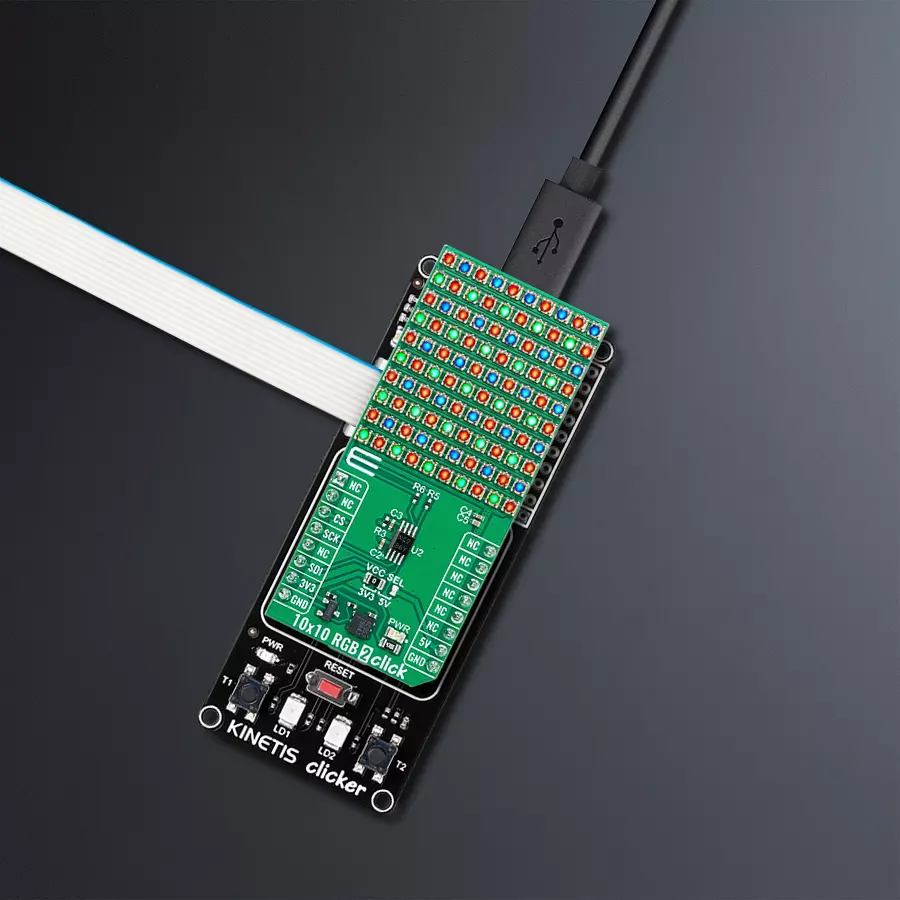
10x10 matrix of "smart" RGB LEDs for various creative and commercial lighting projects

Published Apr 15, 2024
Click board™
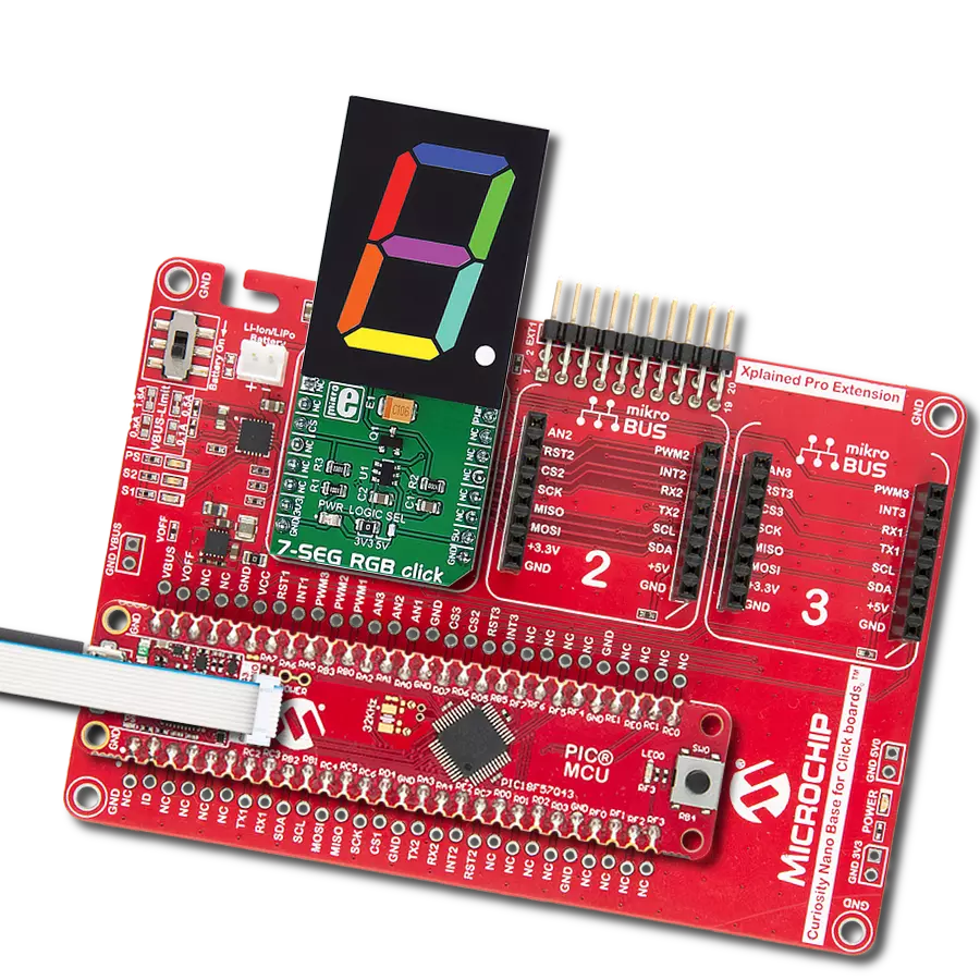
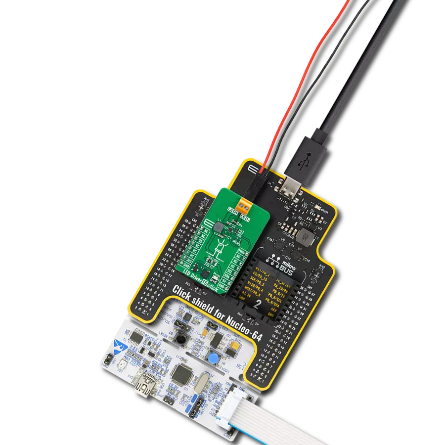
10x10 RGB 2 Click
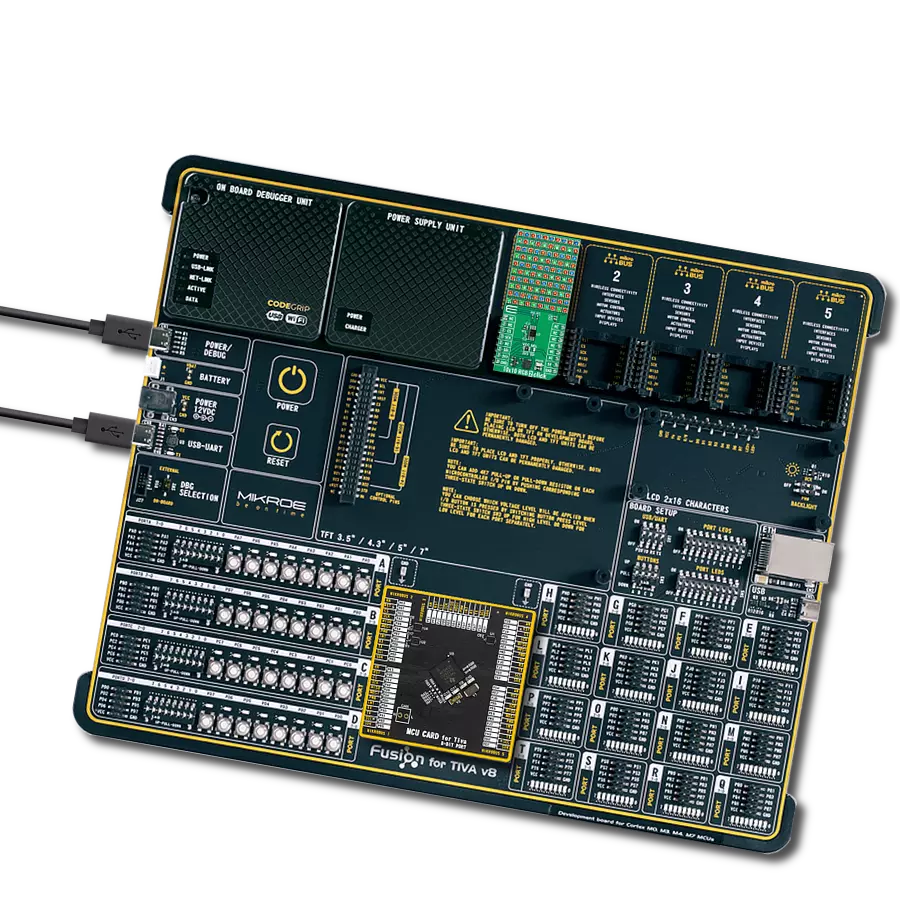
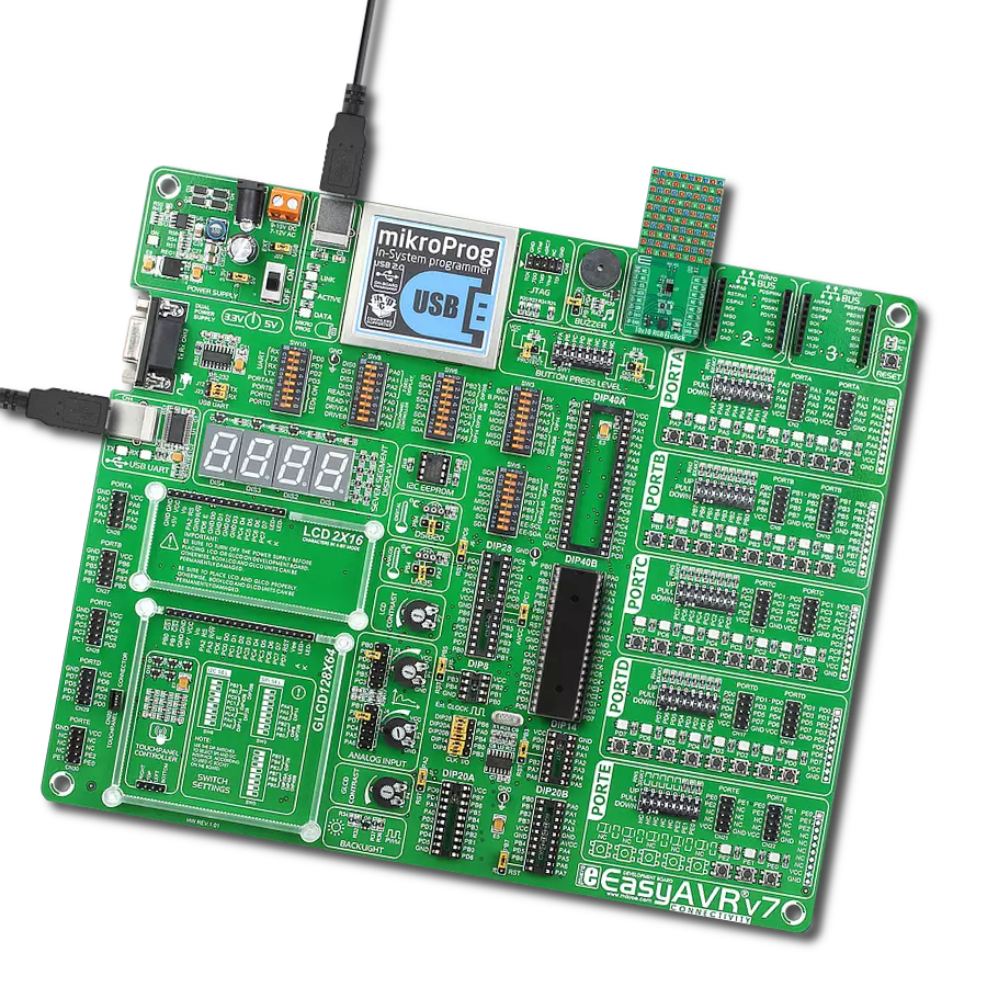
Development board
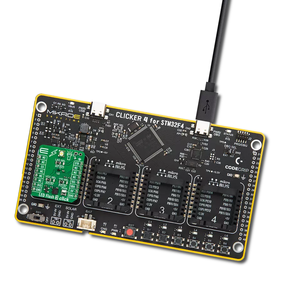
Kinetis Clicker
Compiler
NECTO Studio
MCU
MK22FN512VLH12
Make vibrant, customizable LED displays and lighting systems, perfect for dynamic visual effects and ambient illumination
A
A
Hardware Overview
How does it work?
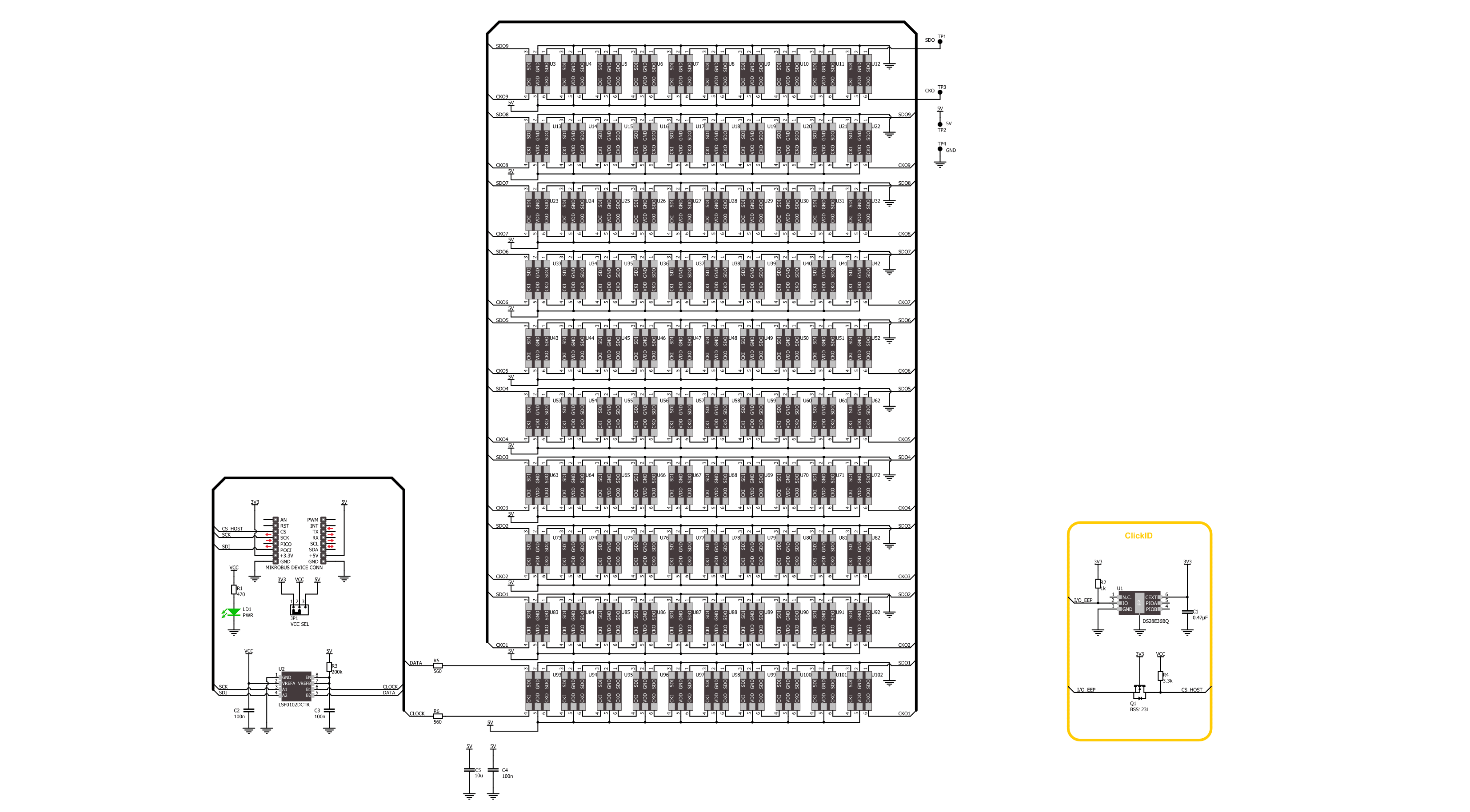
10x10 RGB 2 Click is based on the IN-PC20TBT5R5G5B, an RGB LED with integrated IC from Inolux. At its core, the 10x10 RGB 2 Click showcases a dynamic grid of 100 "smart" RGB LEDs configured into a compact 10x10 display. These LEDs stand out for their dual-wire transmission capability, encompassing a three-channel (RGB) smart control circuit for driving and illumination. Noteworthy features include a signal decoding module, a data buffering system, an inbuilt constant current circuit, and an RC oscillator. The whole solution is tailor-made for various applications, such as LED-based display screens, vibrant LED string lighting, and ambient scene illumination. The IN-PC20TBT5R5G5B is made with
CMOS technology, ensuring minimal voltage requirements and reduced power consumption. It supports 256 grayscale levels for PWM dimming and offers 32 levels of brightness control. The RGB LEDs on the board exhibit distinct characteristics for each color: the red LED operates within a wavelength range of 620-630nm and delivers a light intensity between 100-200mcd, the green LED features a wavelength span of 520-530nm with a brightness of 300-500mcd, and the blue LED emits light in the 460-475nm range with an intensity ranging from 50-100mcd. The diodes are designed to function exclusively on a 5V supply sourced from the mikroBUS™ 5V power rail. To accommodate this, their control is managed through the LSD0102,
a bidirectional voltage-level translator from Texas Instruments. This design choice ensures compatibility with both 3.3V and 5V MCUs, enhancing the board's versatility. A special feature of these diodes is the existence of two output signals, data, and clock, routed on test points next to 5V and GND test points on the back of the board. This Click board™ can operate with either 3.3V or 5V logic voltage levels selected via the VCC SEL jumper. This way, both 3.3V and 5V capable MCUs can use the communication lines properly. Also, this Click board™ comes equipped with a library containing easy-to-use functions and an example code that can be used as a reference for further development.

Features overview
Development board
Kinetis Clicker is a compact starter development board that brings the flexibility of add-on Click boards™ to your favorite microcontroller, making it a perfect starter kit for implementing your ideas. It comes with an onboard 32-bit ARM Cortex-M4 microcontroller, the MK22FN512VLH12 from NXP Semiconductor, a USB connector, LED indicators, buttons, a mikroProg connector, and a header for interfacing with external electronics. Thanks to its compact design with clear and easy-recognizable silkscreen markings, it provides a fluid and immersive working experience, allowing access
anywhere and under any circumstances. Each part of the Kinetis Clicker development kit contains the components necessary for the most efficient operation of the same board. In addition to the possibility of choosing the Kinetis Clicker programming method, using USB HID mikroBootloader, or through an external mikroProg connector for Kinetis programmer, the Clicker board also includes a clean and regulated power supply module for the development kit. The USB-MiniAB connection provides up to 500mA of current, which is more than enough to operate all
onboard and additional modules. All communication methods that mikroBUS™ itself supports are on this board, including the well-established mikroBUS™ socket, reset button, and several buttons and LED indicators. Kinetis Clicker is an integral part of the Mikroe ecosystem, allowing you to create a new application in minutes. Natively supported by Mikroe software tools, it covers many aspects of prototyping thanks to a considerable number of different Click boards™ (over a thousand boards), the number of which is growing every day.

Microcontroller Overview
MCU Card / MCU
Architecture
ARM Cortex-M4
MCU Memory (KB)
512
Silicon Vendor
NXP
Pin count
64
RAM (Bytes)
131072
Used MCU Pins
mikroBUS™ mapper
Take a closer look
Schematic
Step by step
Project assembly

Start by selecting your development board and Click board™. Begin with the Kinetis Clicker as your development board.


Track your results in real time
Application Output
After loading the code example, pressing the "DEBUG" button builds and programs it on the selected setup.

After programming is completed, a header with buttons for various actions available in the IDE appears. By clicking the green "PLAY "button, we start reading the results achieved with Click board™.

Upon completion of programming, the Application Output tab is automatically opened, where the achieved result can be read. In case of an inability to perform the Debug function, check if a proper connection between the MCU used by the setup and the CODEGRIP programmer has been established. A detailed explanation of the CODEGRIP-board connection can be found in the CODEGRIP User Manual. Please find it in the RESOURCES section.

Software Support
Library Description
This library contains API for 10x10 RGB 2 Click driver.
Key functions:
c10x10rgb2_write_char- This function writes a single ASCII character in a 8x8 font sizec10x10rgb2_write_string- This function writes a text string in a 8x8 font size by scrolling characters to the left sidec10x10rgb2_draw_picture- This function draws a 10x10px picture on the screen
Open Source
Code example
This example can be found in NECTO Studio. Feel free to download the code, or you can copy the code below.
/*!
 * @file main.c
 * @brief 10x10 RGB 2 Click example
 *
 * # Description
 * This example demonstrates the use of the 10x10 RGB 2 click board by showing
 * a practical example of using the implemented functions.
 *
 * The demo application is composed of two sections :
 *
 * ## Application Init
 * Initializes the driver and performs the click default configuration.
 *
 * ## Application Task
 * Displays digits 0-9 first, then writes RGB chars and demonstrates the rotation of characters.
 * After that, scrolls the text, displays the MIKROE logo image, and showcases a rainbow demo.
 * All data is logged on the USB UART where you can track the program flow.
 *
 * @author Stefan Filipovic
 *
 */

#include "board.h"
#include "log.h"
#include "c10x10rgb2.h"
#include "c10x10rgb2_resources.h"

static c10x10rgb2_t c10x10rgb2;
static log_t logger;

void application_init ( void )
{
    log_cfg_t log_cfg;  /**< Logger config object. */
    c10x10rgb2_cfg_t c10x10rgb2_cfg;  /**< Click config object. */

    /**
     * Logger initialization.
     * Default baud rate: 115200
     * Default log level: LOG_LEVEL_DEBUG
     * @note If USB_UART_RX and USB_UART_TX
     * are defined as HAL_PIN_NC, you will
     * need to define them manually for log to work.
     * See @b LOG_MAP_USB_UART macro definition for detailed explanation.
     */
    LOG_MAP_USB_UART( log_cfg );
    log_init( &logger, &log_cfg );
    log_info( &logger, " Application Init " );

    // Click initialization.
    c10x10rgb2_cfg_setup( &c10x10rgb2_cfg );
    C10X10RGB2_MAP_MIKROBUS( c10x10rgb2_cfg, MIKROBUS_1 );
    if ( SPI_MASTER_ERROR == c10x10rgb2_init( &c10x10rgb2, &c10x10rgb2_cfg ) )
    {
        log_error( &logger, " Communication init." );
        for ( ; ; );
    }

    if ( C10X10RGB2_ERROR == c10x10rgb2_default_cfg ( &c10x10rgb2 ) )
    {
        log_error( &logger, " Default configuration." );
        for ( ; ; );
    }

    log_info( &logger, " Application Task " );
}

void application_task ( void )
{
    log_printf( &logger, " Writing digits\r\n\n" );
    c10x10rgb2_set_pen ( &c10x10rgb2, C10X10RGB2_COLOR_MAROON, C10X10RGB2_COLOR_BLACK, C10X10RGB2_ROTATION_V_0 );
    for ( uint8_t digit = '0'; digit <= '9'; digit++ )
    {
        c10x10rgb2_write_char ( &c10x10rgb2, digit );
        Delay_ms ( 500 );
    }

    log_printf( &logger, " Writing RGB chars\r\n\n" );
    c10x10rgb2_set_pen ( &c10x10rgb2, C10X10RGB2_COLOR_RED, C10X10RGB2_COLOR_BLACK, C10X10RGB2_ROTATION_V_0 );
    c10x10rgb2_write_char ( &c10x10rgb2, 'R' );
    Delay_ms( 1000 );
    c10x10rgb2_set_pen ( &c10x10rgb2, C10X10RGB2_COLOR_BLACK, C10X10RGB2_COLOR_GREEN, C10X10RGB2_ROTATION_V_0 );
    c10x10rgb2_write_char ( &c10x10rgb2, 'G' );
    Delay_ms( 1000 );
    c10x10rgb2_set_pen ( &c10x10rgb2, C10X10RGB2_COLOR_BLUE, C10X10RGB2_COLOR_BLACK, C10X10RGB2_ROTATION_V_0 );
    c10x10rgb2_write_char ( &c10x10rgb2, 'B' );
    Delay_ms( 1000 );

    log_printf( &logger, " Rotating char\r\n\n" );
    c10x10rgb2_set_pen ( &c10x10rgb2, C10X10RGB2_COLOR_PURPLE, C10X10RGB2_COLOR_BLACK, C10X10RGB2_ROTATION_V_0 );
    c10x10rgb2_write_char ( &c10x10rgb2, 'R' );
    Delay_ms( 500 );
    c10x10rgb2_set_pen ( &c10x10rgb2, C10X10RGB2_COLOR_PURPLE, C10X10RGB2_COLOR_BLACK, C10X10RGB2_ROTATION_H_180 );
    c10x10rgb2_write_char ( &c10x10rgb2, 'R' );
    Delay_ms( 500 );
    c10x10rgb2_set_pen ( &c10x10rgb2, C10X10RGB2_COLOR_PURPLE, C10X10RGB2_COLOR_BLACK, C10X10RGB2_ROTATION_V_180 );
    c10x10rgb2_write_char ( &c10x10rgb2, 'R' );
    Delay_ms( 500 );
    c10x10rgb2_set_pen ( &c10x10rgb2, C10X10RGB2_COLOR_PURPLE, C10X10RGB2_COLOR_BLACK, C10X10RGB2_ROTATION_H_0 );
    c10x10rgb2_write_char ( &c10x10rgb2, 'R' );
    Delay_ms( 500 );
    c10x10rgb2_set_pen ( &c10x10rgb2, C10X10RGB2_COLOR_PURPLE, C10X10RGB2_COLOR_BLACK, C10X10RGB2_ROTATION_V_0 );
    c10x10rgb2_write_char ( &c10x10rgb2, 'R' );
    Delay_ms( 500 );

    log_printf( &logger, " Writing text\r\n\n" );
    c10x10rgb2_set_pen ( &c10x10rgb2, C10X10RGB2_COLOR_OLIVE, C10X10RGB2_COLOR_BLACK, C10X10RGB2_ROTATION_V_0 );
    c10x10rgb2_write_string ( &c10x10rgb2, "MIKROE 10x10 RGB 2", 50 );
    Delay_ms ( 1000 );

    log_printf( &logger, " Drawing MIKROE logo\r\n\n" );
    c10x10rgb2_draw_picture ( &c10x10rgb2, c10x10rgb_img_mikroe );
    Delay_ms( 2000 );

    log_printf( &logger, " Rainbow demo\r\n\n" );
    c10x10rgb2_demo_rainbow ( &c10x10rgb2, 10, 10, 500 );
    Delay_ms( 500 );
}

void main ( void )
{
    application_init( );

    for ( ; ; )
    {
        application_task( );
    }
}

// ------------------------------------------------------------------------ END