Ensure reliable positioning for accurate location awareness with SAM-M10Q and PIC32MZ2048EFM100
High-precision GNSS solution for asset tracking, navigation systems, and location-based services

Published Aug 01, 2024
Click board™
GNSS 18 Click
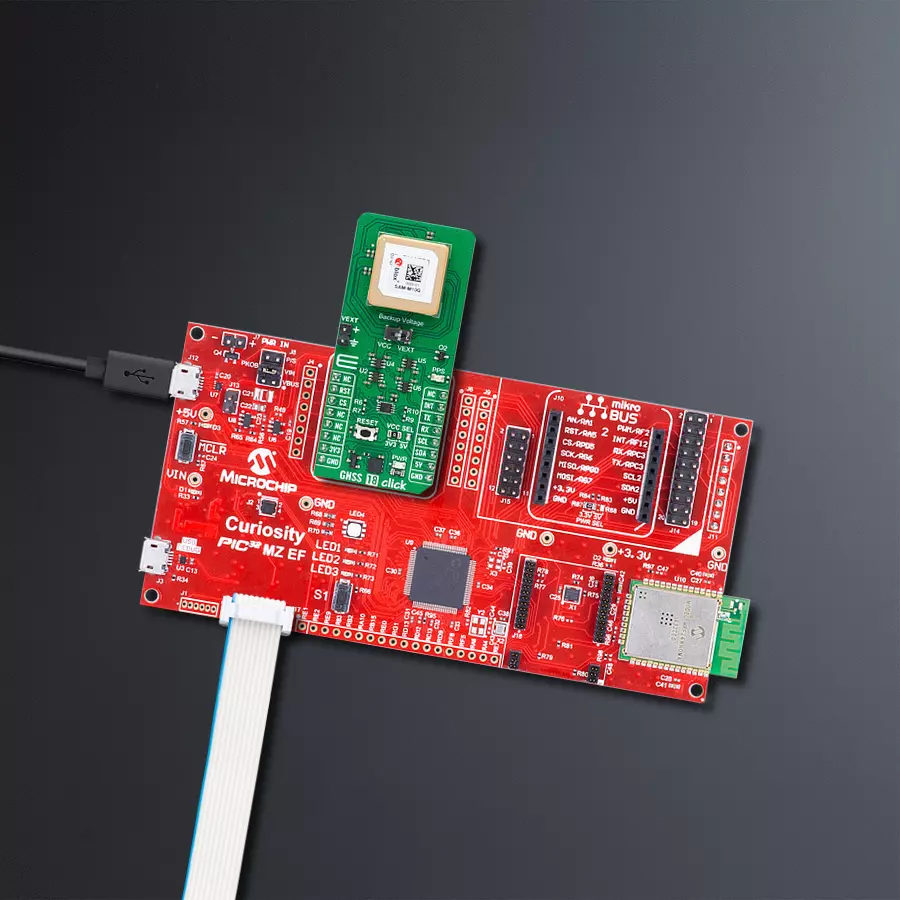
Dev. board
Curiosity PIC32 MZ EF
Compiler
NECTO Studio
MCU
PIC32MZ2048EFM100
Precisely locate and monitor the movement of equipment, vehicles, or personnel in real-time for accurate location awareness
A
A
Hardware Overview
How does it work?
GNSS 18 Click is based on the SAM-M10Q, a high-precision GNSS antenna module from u-blox. This module uses the u-blox M10 standard precision GNSS platform, known for its outstanding sensitivity and rapid acquisition time across all L1 GNSS signals. The M10 platform supports the simultaneous reception of signals from four GNSS systems. By default, the SAM-M10Q-00B is configured to concurrently receive signals from GPS, Galileo, GLONASS, and BeiDou B1C, with additional support for QZSS and SBAS. Its single RF front-end architecture allows it to capture multiple GNSS constellations simultaneously, providing flexibility to configure for a subset of GNSS constellations to optimize power consumption. Accessing many visible satellites ensures the receiver can select the strongest signals, maximizing position availability even in challenging environments like deep urban canyons. u-blox Super-S (Super-Signal) technology enhances the RF sensitivity of the SAM-M10Q module, significantly improving dynamic position accuracy in non-line-of-sight scenarios. Assuming an Airborne 4g platform, the module's operational limits include an altitude capability of up to 80,000 meters and a velocity of up to 500 meters per
second. With a remarkably low power consumption of just 37mW in continuous tracking mode while concurrently tracking four GNSS, this module ensures excellent power efficiency, making it ideal for battery-operated devices like asset trackers without sacrificing GNSS performance. The SAM-M10Q module has an integrated GNSS patch antenna, ensuring optimal signal reception. An internal SAW filter and a low-noise amplifier (LNA) further enhance the RF signal, which provides superior out-band jamming immunity, making it highly effective even when a cellular modem is nearby. The SAM-M10Q is equipped with features to detect jamming and spoofing attempts, promptly reporting these events to the host system to enable an appropriate response. Communication between the SAM-M10Q and the host MCU is made through a UART interface using the standard UART RX and TX pins. The module communicates at 115200bps by default, allowing efficient data exchange. Also, for developers looking to build their software from scratch, the module also includes I2C communication capabilities, operational only in Slave mode, with clock frequencies up to 400kHz. Besides interface pins, this Click board™ also incorporates a reset pin (RST) and RESET button
for direct module resetting and an external interrupt signal (INT) that can be programmed for various functions, such as waking up the module. It also features an orange PPS LED indicator that signals the pulse per second, adjustable to different conditions. This SAM-M10Q also has the possibility of a backup 3V supply from an external source connected to VEXT pins. The main and backup power source can be selected via the Backup Voltage switch, which can be placed in the desired position: VCC for the internal and VEXT for an external power source. This Click board™ can operate with both 3.3V and 5V logic voltage levels selected via the VCC SEL jumper. Given that the SAM-M10Q module operates at 3.3V, a pack of logic-level translators, PCA9306 and several SN74LVC1T45s, are also used for proper operation and an accurate signal-level translation. This way, both 3.3V and 5V capable MCUs can use the communication lines properly. Also, this Click board™ comes equipped with a library containing easy-to-use functions and an example code that can be used as a reference for further development.

Features overview
Development board
Curiosity PIC32 MZ EF development board is a fully integrated 32-bit development platform featuring the high-performance PIC32MZ EF Series (PIC32MZ2048EFM) that has a 2MB Flash, 512KB RAM, integrated FPU, Crypto accelerator, and excellent connectivity options. It includes an integrated programmer and debugger, requiring no additional hardware. Users can expand
functionality through MIKROE mikroBUS™ Click™ adapter boards, add Ethernet connectivity with the Microchip PHY daughter board, add WiFi connectivity capability using the Microchip expansions boards, and add audio input and output capability with Microchip audio daughter boards. These boards are fully integrated into PIC32’s powerful software framework, MPLAB Harmony,
which provides a flexible and modular interface to application development a rich set of inter-operable software stacks (TCP-IP, USB), and easy-to-use features. The Curiosity PIC32 MZ EF development board offers expansion capabilities making it an excellent choice for a rapid prototyping board in Connectivity, IOT, and general-purpose applications.

Microcontroller Overview
MCU Card / MCU

Architecture
PIC32
MCU Memory (KB)
2048
Silicon Vendor
Microchip
Pin count
100
RAM (Bytes)
524288
Used MCU Pins
mikroBUS™ mapper
Take a closer look
Click board™ Schematic

Step by step
Project assembly

Start by selecting your development board and Click board™. Begin with the Curiosity PIC32 MZ EF as your development board.


Track your results in real time
Application Output
1. Application Output - In Debug mode, the 'Application Output' window enables real-time data monitoring, offering direct insight into execution results. Ensure proper data display by configuring the environment correctly using the provided tutorial.

2. UART Terminal - Use the UART Terminal to monitor data transmission via a USB to UART converter, allowing direct communication between the Click board™ and your development system. Configure the baud rate and other serial settings according to your project's requirements to ensure proper functionality. For step-by-step setup instructions, refer to the provided tutorial.

3. Plot Output - The Plot feature offers a powerful way to visualize real-time sensor data, enabling trend analysis, debugging, and comparison of multiple data points. To set it up correctly, follow the provided tutorial, which includes a step-by-step example of using the Plot feature to display Click board™ readings. To use the Plot feature in your code, use the function: plot(*insert_graph_name*, variable_name);. This is a general format, and it is up to the user to replace 'insert_graph_name' with the actual graph name and 'variable_name' with the parameter to be displayed.

Software Support
Library Description
This library contains API for GNSS 18 Click driver.
Key functions:
gnss18_generic_read- This function reads a desired number of data bytes from the module.gnss18_reset_device- This function resets the device by toggling the RST pin.gnss18_parse_gpgga- This function parses the GPGGA data from the read response buffer.
Open Source
Code example
The complete application code and a ready-to-use project are available through the NECTO Studio Package Manager for direct installation in the NECTO Studio. The application code can also be found on the MIKROE GitHub account.
/*!
 * @file main.c
 * @brief GNSS 18 Click example
 *
 * # Description
 * This example demonstrates the use of GNSS 18 Click by reading and displaying
 * the GNSS coordinates.
 *
 * The demo application is composed of two sections :
 *
 * ## Application Init
 * Initializes the driver and resets the Click board.
 *
 * ## Application Task
 * Reads the received data, parses the GPGGA info from it, and once it receives the position fix
 * it will start displaying the coordinates on the USB UART.
 *
 * ## Additional Function
 * - static void gnss18_clear_app_buf ( void )
 * - static err_t gnss18_process ( gnss18_t *ctx )
 * - static void gnss18_parser_application ( uint8_t *rsp )
 *
 * @author Stefan Ilic
 *
 */

#include "board.h"
#include "log.h"
#include "gnss18.h"

#define PROCESS_BUFFER_SIZE 300

static gnss18_t gnss18;
static log_t logger;

static uint8_t app_buf[ PROCESS_BUFFER_SIZE ] = { 0 };
static int32_t app_buf_len = 0;

/**
 * @brief GNSS 18 clearing application buffer.
 * @details This function clears memory of application buffer and reset its length and counter.
 * @return None.
 * @note None.
 */
static void gnss18_clear_app_buf ( void );

/**
 * @brief GNSS 18 data reading function.
 * @details This function reads data from device and concatenates data to application buffer.
 * @param[in] ctx : Click context object.
 * See #gnss18_t object definition for detailed explanation.
 * @return @li @c  0 - Read some data.
 *         @li @c -1 - Nothing is read or Application buffer overflow.
 * See #err_t definition for detailed explanation.
 * @note None.
 */
static err_t gnss18_process ( gnss18_t *ctx );

/**
 * @brief GNSS 18 parser application.
 * @param[in] rsp Response buffer.
 * @details This function logs GNSS data on the USB UART.
 * @return None.
 * @note None.
 */
static void gnss18_parser_application ( uint8_t *rsp );

void application_init ( void )
{
    log_cfg_t log_cfg;  /**< Logger config object. */
    gnss18_cfg_t gnss18_cfg;  /**< Click config object. */

    /**
     * Logger initialization.
     * Default baud rate: 115200
     * Default log level: LOG_LEVEL_DEBUG
     * @note If USB_UART_RX and USB_UART_TX
     * are defined as HAL_PIN_NC, you will
     * need to define them manually for log to work.
     * See @b LOG_MAP_USB_UART macro definition for detailed explanation.
     */
    LOG_MAP_USB_UART( log_cfg );
    log_init( &logger, &log_cfg );
    log_info( &logger, " Application Init " );

    // Click initialization.
    gnss18_cfg_setup( &gnss18_cfg );
    GNSS18_MAP_MIKROBUS( gnss18_cfg, MIKROBUS_1 );
    err_t init_flag = gnss18_init( &gnss18, &gnss18_cfg );
    if ( ( UART_ERROR == init_flag ) || ( I2C_MASTER_ERROR == init_flag ) )
    {
        log_error( &logger, " Communication init." );
        for ( ; ; );
    }

    log_info( &logger, " Application Task " );
}

void application_task ( void )
{
    if ( GNSS18_OK == gnss18_process( &gnss18 ) )
    {
        if ( PROCESS_BUFFER_SIZE == app_buf_len )
        {
            gnss18_parser_application( app_buf );
        }
    }
}

int main ( void )
{
    /* Do not remove this line or clock might not be set correctly. */
    #ifdef PREINIT_SUPPORTED
    preinit();
    #endif

    application_init( );

    for ( ; ; )
    {
        application_task( );
    }

    return 0;
}

static void gnss18_clear_app_buf ( void )
{
    memset( app_buf, 0, app_buf_len );
    app_buf_len = 0;
}

static err_t gnss18_process ( gnss18_t *ctx )
{
    int32_t rx_size = 0;
    uint8_t rx_buf[ PROCESS_BUFFER_SIZE ] = { 0 };
    if ( GNSS18_DRV_SEL_UART == ctx->drv_sel )
    {
        rx_size = gnss18_generic_read( ctx, rx_buf, PROCESS_BUFFER_SIZE );
    }
    else
    {
        if ( GNSS18_OK == gnss18_generic_read( ctx, rx_buf, 1 ) )
        {
            if ( GNSS18_DUMMY != rx_buf[ 0 ] )
            {
                rx_size = 1;
            }
        }
    }
    if ( rx_size > 0 )
    {
        int32_t buf_cnt = app_buf_len;
        if ( ( ( app_buf_len + rx_size ) > PROCESS_BUFFER_SIZE ) && ( app_buf_len > 0 ) )
        {
            buf_cnt = PROCESS_BUFFER_SIZE - ( ( app_buf_len + rx_size ) - PROCESS_BUFFER_SIZE );
            memmove ( app_buf, &app_buf[ PROCESS_BUFFER_SIZE - buf_cnt ], buf_cnt );
        }
        for ( int32_t rx_cnt = 0; rx_cnt < rx_size; rx_cnt++ )
        {
            if ( rx_buf[ rx_cnt ] )
            {
                app_buf[ buf_cnt++ ] = rx_buf[ rx_cnt ];
                if ( app_buf_len < PROCESS_BUFFER_SIZE )
                {
                    app_buf_len++;
                }
            }
        }
        return GNSS18_OK;
    }
    return GNSS18_ERROR;
}

static void gnss18_parser_application ( uint8_t *rsp )
{
    uint8_t element_buf[ 100 ] = { 0 };
    if ( GNSS18_OK == gnss18_parse_gpgga( rsp, GNSS18_GPGGA_LATITUDE, element_buf ) )
    {
        static uint8_t wait_for_fix_cnt = 0;
        if ( ( strlen( element_buf ) > 0 ) )
        {
            log_printf( &logger, "\r\n Latitude: %.2s degrees, %s minutes \r\n", element_buf, &element_buf[ 2 ] );
            gnss18_parse_gpgga( rsp, GNSS18_GPGGA_LONGITUDE, element_buf );
            log_printf( &logger, " Longitude: %.3s degrees, %s minutes \r\n", element_buf, &element_buf[ 3 ] );
            memset( element_buf, 0, sizeof( element_buf ) );
            gnss18_parse_gpgga( rsp, GNSS18_GPGGA_ALTITUDE, element_buf );
            log_printf( &logger, " Altitude: %s m \r\n", element_buf );
            wait_for_fix_cnt = 0;
        }
        else
        {
            if ( wait_for_fix_cnt % 5 == 0 )
            {
                log_printf( &logger, " Waiting for the position fix...\r\n\n" );
                wait_for_fix_cnt = 0;
            }
            wait_for_fix_cnt++;
        }
        gnss18_clear_app_buf(  );
    }
}

// ------------------------------------------------------------------------ END


