Increase accuracy and reliability in global positioning across different regions and conditions with Mosaic-x5 and PIC32MZ1024EFH064
Compact global navigation satellite system (GNSS) receiver

Published Apr 09, 2024
Click board™
Mosaic Click
Dev. board
PIC32MZ clicker
Compiler
NECTO Studio
MCU
PIC32MZ1024EFH064
Provide precise navigation and location-based applications through high-quality global positioning, using multi-band and multi-constellation GNSS satellite signal tracking
A
A
Hardware Overview
How does it work?
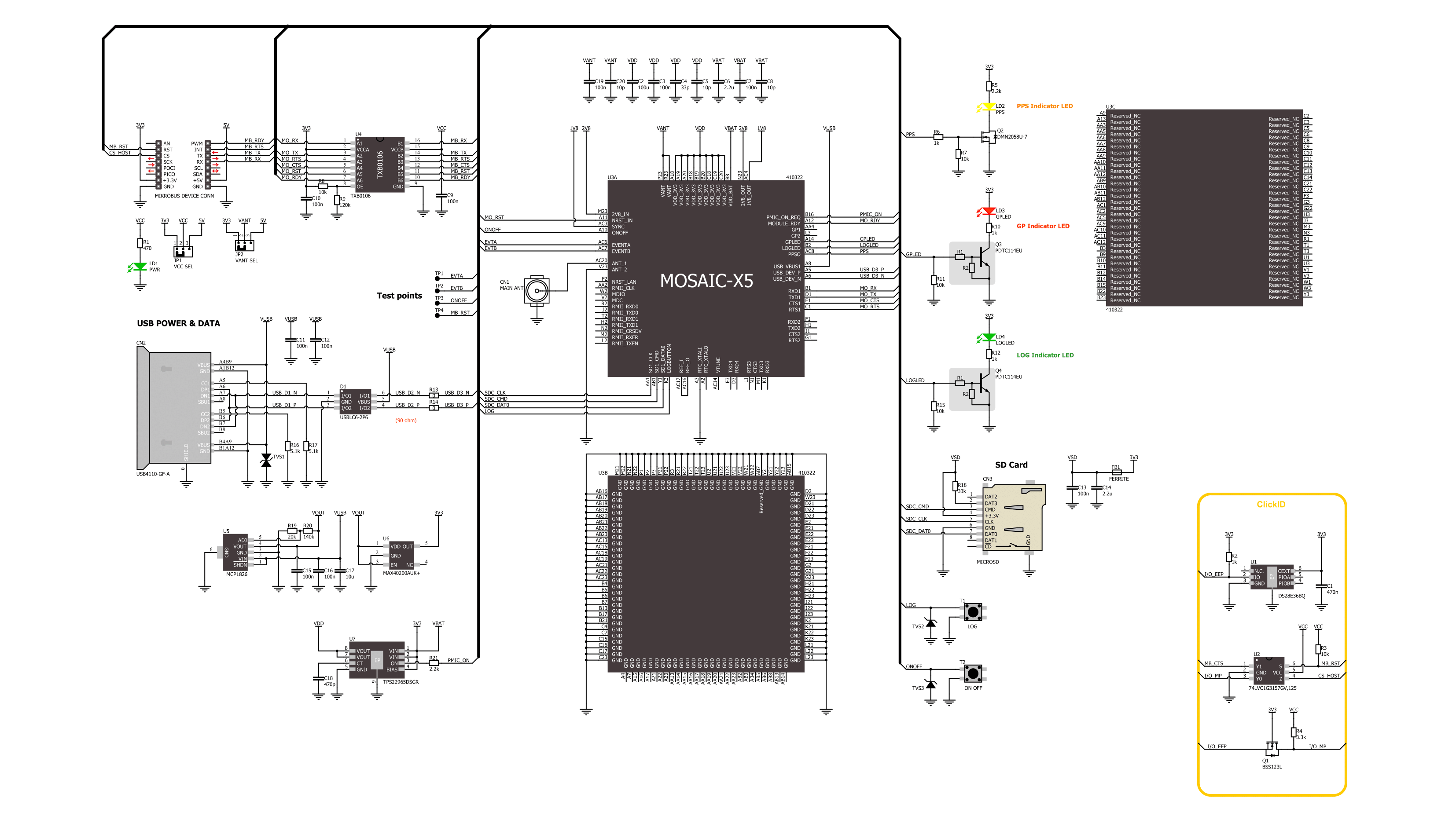
Mosaic Click is based on the Mosaic-X5, a compact GNSS receiver from Septentrio. This receiver offers centimeter-level accuracy across multiple bands and satellite constellations such as GPS, GLONASS, Beidou, Galileo, and NavIC. It integrates AIM+ technology for advanced interference mitigation and anti-spoofing, providing unmatched reliability and precision. This technology can neutralize diverse signal interferences, ranging from simple, continuous narrowband signals to complex wideband and pulsed jammers. Designed for mass-market applications like robotics and autonomous technologies, this solution not only ensures low power consumption but also offers a wide range of interface options and delivers RTK positioning. Communication between the Mosaic-X5 and the host MCU is made through a UART interface, using the standard UART RX and TX pins and hardware flow control pins (CTS/RTS). The module communicates at 115200bps by default, allowing efficient data exchange. This Click board™ also incorporates a reset pin (RST) for direct module resetting and a ready indicator (RDY) that signals the module's operational status through logical high
(active) or low (standby or reset) states. Furthermore, the module supports USB connectivity in device mode, adhering to the USB 2.0 standard for high-speed data transfers (up to 480Mbps). It includes options for USB power achieved by an LDO (the MCP1826) or an alternative power switch (the TPS22965), each ensuring the required 3.3V for normal module operation. In addition to the USB interface, it is also equipped with a microSD card slot for external data logging, which can be controlled via a LOG button. This button enables the toggling of SD card logging and manages the card's mounting status, which can be monitored through a green LED indicator marked LOG. If the LOG button is pressed for 100ms to 5 seconds, it toggles SD Card logging ON and OFF. Holding this button for more than 5 seconds and then releasing it unmounts the SD card if it is mounted, and vice versa. The green LOG LED indicator can check the SD card mount status. In addition to the LOG LED, the board also features a general-purpose user-configurable red LED, a yellow PPS (Pulse Per Second) LED, and four test points. TP1 and TP2 are two event timers that can be used to time tag external events with a
time resolution of 20ns, while TR3 and TP4 present the same functions as ON/OFF and Reset features. It is also possible to power off the module with the ON/OFF button and to toggle it between active and standby mode. However, this abrupt power interruption could cause data losses when logging on an external SD card. The board features a u.Fl connector for a GNSS antenna, like the GNSS Active External Antenna that MIKROE offers, in combination with an IPEX-SMA cable for flexible and efficient connectivity options. In addition, the user can easily choose the external antenna's power supply by choosing between 3.3V and 5V on the VANT SEL jumper. This Click board™ can operate with both 3.3V and 5V logic voltage levels selected via the VCC SEL jumper. Given that the Mosaic-X5 module operates at 3.3V, a logic-level translator, TXB0106, is also used for proper operation and an accurate signal-level translation. This way, both 3.3V and 5V capable MCUs can use the communication lines properly. Also, this Click board™ comes equipped with a library containing easy-to-use functions and an example code that can be used as a reference for further development.

Features overview
Development board
PIC32MZ Clicker is a compact starter development board that brings the flexibility of add-on Click boards™ to your favorite microcontroller, making it a perfect starter kit for implementing your ideas. It comes with an onboard 32-bit PIC32MZ microcontroller with FPU from Microchip, a USB connector, LED indicators, buttons, a mikroProg connector, and a header for interfacing with external electronics. Thanks to its compact design with clear and easy-recognizable silkscreen markings, it provides a fluid and immersive working experience, allowing access anywhere and under
any circumstances. Each part of the PIC32MZ Clicker development kit contains the components necessary for the most efficient operation of the same board. In addition to the possibility of choosing the PIC32MZ Clicker programming method, using USB HID mikroBootloader, or through an external mikroProg connector for PIC, dsPIC, or PIC32 programmer, the Clicker board also includes a clean and regulated power supply module for the development kit. The USB Micro-B connection can provide up to 500mA of current, which is more than enough to operate all onboard
and additional modules. All communication methods that mikroBUS™ itself supports are on this board, including the well-established mikroBUS™ socket, reset button, and several buttons and LED indicators. PIC32MZ Clicker is an integral part of the Mikroe ecosystem, allowing you to create a new application in minutes. Natively supported by Mikroe software tools, it covers many aspects of prototyping thanks to a considerable number of different Click boards™ (over a thousand boards), the number of which is growing every day.

Microcontroller Overview
MCU Card / MCU

Architecture
PIC32
MCU Memory (KB)
1024
Silicon Vendor
Microchip
Pin count
64
RAM (Bytes)
524288
You complete me!
Accessories
GNSS Active External Antenna is a unique multi-band type of antenna coming from u-blox that is the perfect selection for high precision GNSS applications, which require highly accurate location abilities such as RTK. The ANN-MB-00 is a multi-band (L1, L2/E5b/B2I) active GNSS antenna with a 5m cable and SMA connector. The antenna supports GPS, GLONASS, Galileo, and BeiDou and includes a high-performance multi-band RHCP dual-feed patch antenna element, a built-in high-gain LNA with SAW pre-filtering, and a 5 m antenna cable with SMA connector, and is waterproof.

Used MCU Pins
mikroBUS™ mapper
Take a closer look
Click board™ Schematic
Step by step
Project assembly

Start by selecting your development board and Click board™. Begin with the PIC32MZ clicker as your development board.


Software Support
Library Description
This library contains API for Mosaic Click driver.
Key functions:
mosaic_generic_read- This function reads a desired number of data bytes by using UART serial interfacemosaic_enable_nmea_output- This function enables the NMEA output with the selected message parameters and an output intervalmosaic_parse_gga- This function parses the GGA data from the read response buffer
Open Source
Code example
The complete application code and a ready-to-use project are available through the NECTO Studio Package Manager for direct installation in the NECTO Studio. The application code can also be found on the MIKROE GitHub account.
/*!
 * @file main.c
 * @brief Mosaic Click Example.
 *
 * # Description
 * This example demonstrates the use of Mosaic Click by reading and displaying
 * the GNSS coordinates.
 *
 * The demo application is composed of two sections :
 *
 * ## Application Init
 * Initializes the driver, reads the NMEA version, and enables the NMEA output.
 *
 * ## Application Task
 * Reads the received data, parses the NMEA GGA info from it, and once it receives
 * the position fix it will start displaying the coordinates on the USB UART.
 *
 * ## Additional Function
 * - static void mosaic_clear_app_buf ( void )
 * - static void mosaic_log_app_buf ( void )
 * - static err_t mosaic_process ( mosaic_t *ctx )
 * - static err_t mosaic_wait_prompt ( mosaic_t *ctx )
 * - static void mosaic_parser_application ( uint8_t *rsp )
 *
 * @author Stefan Filipovic
 *
 */

#include "board.h"
#include "log.h"
#include "mosaic.h"

// Application buffer size
#define APP_BUFFER_SIZE             500
#define PROCESS_BUFFER_SIZE         200

static mosaic_t mosaic;
static log_t logger;

static uint8_t app_buf[ APP_BUFFER_SIZE ] = { 0 };
static int32_t app_buf_len = 0;

/**
 * @brief Mosaic clearing application buffer.
 * @details This function clears memory of application buffer and reset its length.
 * @note None.
 */
static void mosaic_clear_app_buf ( void );

/**
 * @brief Mosaic log application buffer.
 * @details This function logs data from application buffer to USB UART.
 * @note None.
 */
static void mosaic_log_app_buf ( void );

/**
 * @brief Mosaic data reading function.
 * @details This function reads data from device and concatenates data to application buffer.
 * @param[in] ctx : Click context object.
 * See #mosaic_t object definition for detailed explanation.
 * @return @li @c  0 - Read some data.
 *         @li @c -1 - Nothing is read.
 * See #err_t definition for detailed explanation.
 * @note None.
 */
static err_t mosaic_process ( mosaic_t *ctx );

/**
 * @brief Mosaic wait prompt function.
 * @details This function waits for a "COM1>" prompt string to appear on UART which indicates
 * the device is ready to receive commands.
 * @param[in] ctx : Click context object.
 * See #mosaic_t object definition for detailed explanation.
 * @return @li @c  0 - Prompt (COM1>) read successfully.
 *         @li @c -2 - Timeout error.
 * See #err_t definition for detailed explanation.
 * @note None.
 */
static err_t mosaic_wait_prompt ( mosaic_t *ctx );

/**
 * @brief Mosaic parser application.
 * @param[in] rsp Response buffer.
 * @details This function logs GNSS data on the USB UART.
 * @return None.
 * @note None.
 */
static void mosaic_parser_application ( uint8_t *rsp );

void application_init ( void )
{
    log_cfg_t log_cfg;  /**< Logger config object. */
    mosaic_cfg_t mosaic_cfg;  /**< Click config object. */

    /**
     * Logger initialization.
     * Default baud rate: 115200
     * Default log level: LOG_LEVEL_DEBUG
     * @note If USB_UART_RX and USB_UART_TX
     * are defined as HAL_PIN_NC, you will
     * need to define them manually for log to work.
     * See @b LOG_MAP_USB_UART macro definition for detailed explanation.
     */
    LOG_MAP_USB_UART( log_cfg );
    log_init( &logger, &log_cfg );
    log_info( &logger, " Application Init " );

    // Click initialization.
    mosaic_cfg_setup( &mosaic_cfg );
    MOSAIC_MAP_MIKROBUS( mosaic_cfg, MIKROBUS_1 );
    if ( UART_ERROR == mosaic_init( &mosaic, &mosaic_cfg ) )
    {
        log_error( &logger, " Communication init." );
        for ( ; ; );
    }

    if ( MOSAIC_OK != mosaic_wait_prompt( &mosaic ) )
    {
        log_error( &logger, " No connection prompt detected." );
        for ( ; ; );
    }
    mosaic_log_app_buf( );
    mosaic_clear_app_buf( );
    Delay_ms ( 100 );

    mosaic_send_cmd( &mosaic, MOSAIC_CMD_GET_NMEA_VERSION );
    mosaic_wait_prompt( &mosaic );
    mosaic_log_app_buf( );
    mosaic_clear_app_buf( );
    Delay_ms ( 100 );

    mosaic_enable_nmea_output( &mosaic, MOSAIC_SNO_MESSAGES_GGA, MOSAIC_SNO_INTERVAL_SEC1 );
    mosaic_wait_prompt( &mosaic );
    mosaic_log_app_buf( );
    mosaic_clear_app_buf( );
    Delay_ms ( 100 );

    log_info( &logger, " Application Task " );
}

void application_task ( void )
{
    mosaic_process( &mosaic );
    if ( app_buf_len > ( sizeof ( MOSAIC_NMEA_GGA ) + MOSAIC_GGA_ELEMENT_SIZE ) )
    {
        mosaic_parser_application( app_buf );
    }
}

int main ( void )
{
    /* Do not remove this line or clock might not be set correctly. */
    #ifdef PREINIT_SUPPORTED
    preinit();
    #endif

    application_init( );

    for ( ; ; )
    {
        application_task( );
    }

    return 0;
}

static void mosaic_clear_app_buf ( void )
{
    memset( app_buf, 0, app_buf_len );
    app_buf_len = 0;
}

static void mosaic_log_app_buf ( void )
{
    for ( int32_t buf_cnt = 0; buf_cnt < app_buf_len; buf_cnt++ )
    {
        log_printf( &logger, "%c", app_buf[ buf_cnt ] );
    }
    log_printf( &logger, "\r\n" );
}

static err_t mosaic_process ( mosaic_t *ctx )
{
    uint8_t rx_buf[ PROCESS_BUFFER_SIZE ] = { 0 };
    int32_t overflow_bytes = 0;
    int32_t rx_cnt = 0;
    int32_t rx_size = mosaic_generic_read( ctx, rx_buf, PROCESS_BUFFER_SIZE );
    if ( ( rx_size > 0 ) && ( rx_size <= APP_BUFFER_SIZE ) )
    {
        if ( ( app_buf_len + rx_size ) > APP_BUFFER_SIZE )
        {
            overflow_bytes = ( app_buf_len + rx_size ) - APP_BUFFER_SIZE;
            app_buf_len = APP_BUFFER_SIZE - rx_size;
            memmove ( app_buf, &app_buf[ overflow_bytes ], app_buf_len );
            memset ( &app_buf[ app_buf_len ], 0, overflow_bytes );
        }
        for ( rx_cnt = 0; rx_cnt < rx_size; rx_cnt++ )
        {
            if ( rx_buf[ rx_cnt ] )
            {
                app_buf[ app_buf_len++ ] = rx_buf[ rx_cnt ];
            }
        }
        return MOSAIC_OK;
    }
    return MOSAIC_ERROR;
}

static err_t mosaic_wait_prompt ( mosaic_t *ctx )
{
    uint32_t timeout_cnt = 0;
    uint32_t timeout = 120000;
    mosaic_process( ctx );
    while ( 0 == strstr( app_buf, MOSAIC_PROMPT_CMD ) )
    {
        mosaic_process( ctx );
        if ( timeout_cnt++ > timeout )
        {
            mosaic_clear_app_buf( );
            return MOSAIC_ERROR_TIMEOUT;
        }
        Delay_ms ( 1 );
    }
    return MOSAIC_OK;
}

static void mosaic_parser_application ( uint8_t *rsp )
{
    uint8_t element_buf[ 100 ] = { 0 };
    if ( MOSAIC_OK == mosaic_parse_gga( rsp, MOSAIC_GGA_LATITUDE, element_buf ) )
    {
        static uint8_t wait_for_fix_cnt = 0;
        if ( strlen( element_buf ) > 0 )
        {
            log_printf( &logger, "\r\n Latitude: %.2s degrees, %s minutes \r\n", element_buf, &element_buf[ 2 ] );
            memset( element_buf, 0, sizeof( element_buf ) );
            mosaic_parse_gga( rsp, MOSAIC_GGA_LONGITUDE, element_buf );
            log_printf( &logger, " Longitude: %.3s degrees, %s minutes \r\n", element_buf, &element_buf[ 3 ] );
            memset( element_buf, 0, sizeof( element_buf ) );
            mosaic_parse_gga( rsp, MOSAIC_GGA_ALTITUDE, element_buf );
            log_printf( &logger, " Altitude: %s m \r\n", element_buf );
            wait_for_fix_cnt = 0;
        }
        else
        {
            if ( wait_for_fix_cnt % 5 == 0 )
            {
                log_printf( &logger, " Waiting for the position fix...\r\n\n" );
                wait_for_fix_cnt = 0;
            }
            wait_for_fix_cnt++;
        }
        mosaic_clear_app_buf(  );
    }
}

// ------------------------------------------------------------------------ END
Additional Support
Resources
Category:GPS/GNSS


