Monitor and assess the levels of pollutants with MQ-135 and PIC32MZ1024EFH064
Your trusted ally in the pursuit of purer air

Published Jun 20, 2023
Click board™
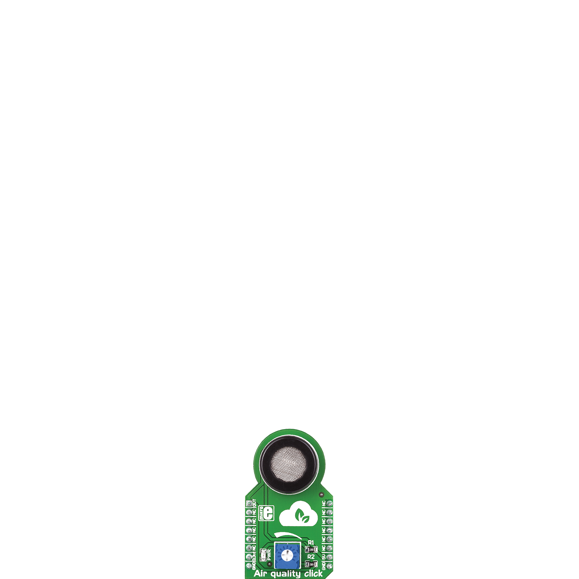
Air quality Click
Dev. board
PIC32MZ clicker
Compiler
NECTO Studio
MCU
PIC32MZ1024EFH064
By providing real-time monitoring and analysis of air pollutants, this air quality solution aims to protect human health and well-being, reducing the risk of respiratory issues, allergies, and other adverse health effects associated with poor air quality
A
A
Hardware Overview
How does it work?
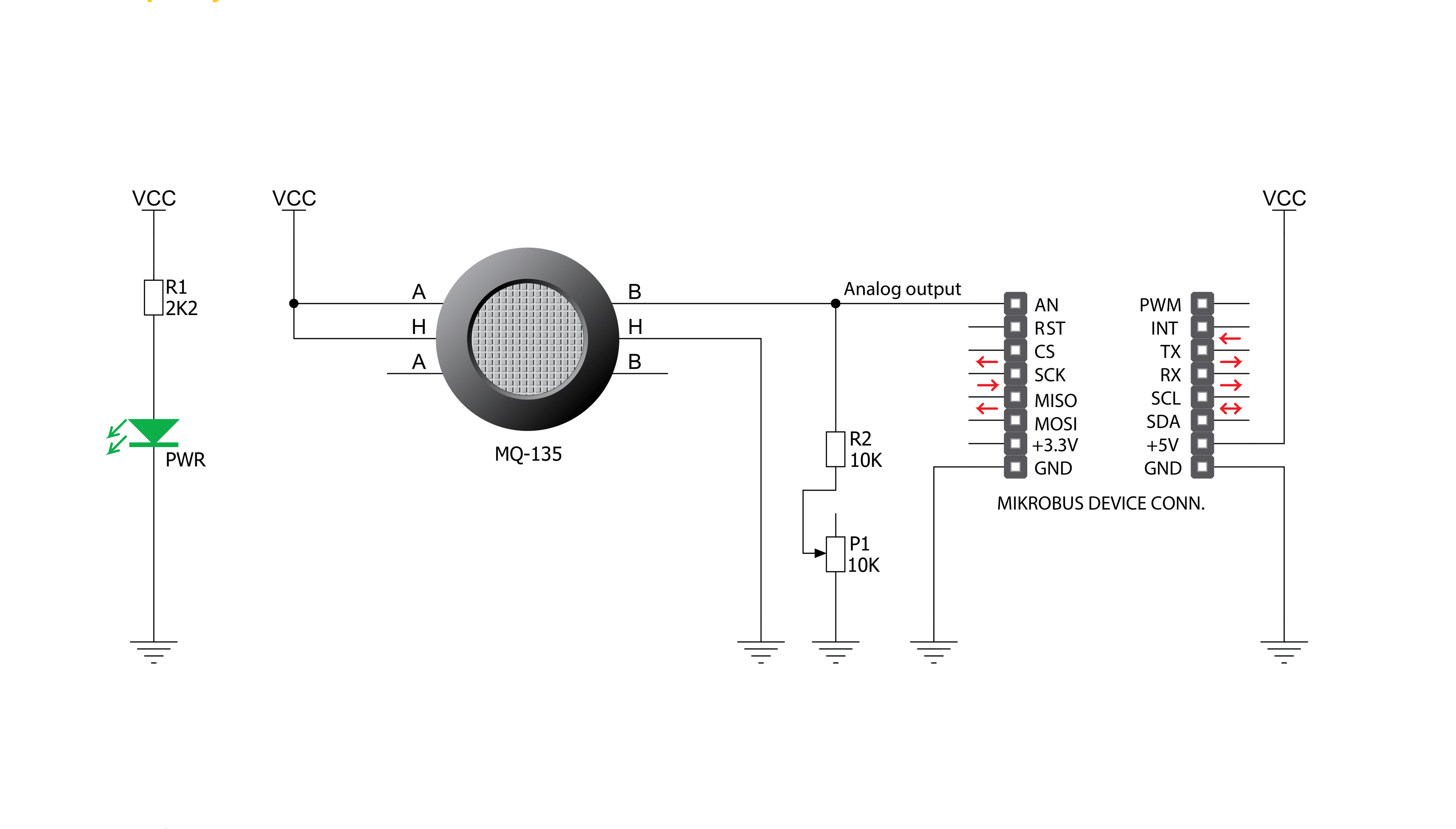
Air Quality Click is based on the MQ-135, an air quality sensor module for poisonous gases from Zhengzhou Winsen Electronics Technology. The MQ-135 can detect the presence and concentration of toxic gases in the air, such as ammonia gas, sulfide, and benzene steam. It consists of a tin dioxide sensitive layer (SnO2) inside an aluminum oxide AL2O3 ceramic tube (measuring electrodes) alongside a heating element inside its tubular casing. The heater is fixed into a plastic and stainless steel net crust, providing necessary work
conditions for sensitive components. Besides its high sensitivity, the MQ-135 is also characterized by a detection range from 10 to 1000ppm for ammonia gas, toluene, hydrogen, and smoke. The MQ-3 provides an analog representation of polluted concentration in the air sent directly to an analog pin of the mikroBUS™ socket labeled OUT. The analog output voltage the sensor provides varies in proportion to the toxic gas concentration; the higher the toxic gas concentration in the air, the higher the output voltage. Also, this Click board™ has a
built-in potentiometer that allows users to adjust the load resistance of the MQ-135 circuit for optimum performance. This Click board™ can be operated only with a 5V logic voltage level. The board must perform appropriate logic voltage level conversion before using MCUs with different logic levels. However, the Click board™ comes equipped with a library containing functions and an example code that can be used, as a reference, for further development.

Features overview
Development board
PIC32MZ Clicker is a compact starter development board that brings the flexibility of add-on Click boards™ to your favorite microcontroller, making it a perfect starter kit for implementing your ideas. It comes with an onboard 32-bit PIC32MZ microcontroller with FPU from Microchip, a USB connector, LED indicators, buttons, a mikroProg connector, and a header for interfacing with external electronics. Thanks to its compact design with clear and easy-recognizable silkscreen markings, it provides a fluid and immersive working experience, allowing access anywhere and under
any circumstances. Each part of the PIC32MZ Clicker development kit contains the components necessary for the most efficient operation of the same board. In addition to the possibility of choosing the PIC32MZ Clicker programming method, using USB HID mikroBootloader, or through an external mikroProg connector for PIC, dsPIC, or PIC32 programmer, the Clicker board also includes a clean and regulated power supply module for the development kit. The USB Micro-B connection can provide up to 500mA of current, which is more than enough to operate all onboard
and additional modules. All communication methods that mikroBUS™ itself supports are on this board, including the well-established mikroBUS™ socket, reset button, and several buttons and LED indicators. PIC32MZ Clicker is an integral part of the Mikroe ecosystem, allowing you to create a new application in minutes. Natively supported by Mikroe software tools, it covers many aspects of prototyping thanks to a considerable number of different Click boards™ (over a thousand boards), the number of which is growing every day.

Microcontroller Overview
MCU Card / MCU

Architecture
PIC32
MCU Memory (KB)
1024
Silicon Vendor
Microchip
Pin count
64
RAM (Bytes)
524288
Used MCU Pins
mikroBUS™ mapper
Take a closer look
Click board™ Schematic
Step by step
Project assembly

Start by selecting your development board and Click board™. Begin with the PIC32MZ clicker as your development board.


Software Support
Library Description
This library contains API for Air Quality Click driver.
Key functions:
airquality_read_an_pin_value- This function reads results of AD conversion of the AN pinairquality_read_an_pin_voltage- This function reads results of AD conversion of the AN pin and converts them to proportional voltage level
Open Source
Code example
The complete application code and a ready-to-use project are available through the NECTO Studio Package Manager for direct installation in the NECTO Studio. The application code can also be found on the MIKROE GitHub account.
/*!
 * @file main.c
 * @brief Air quality Click Example.
 *
 * # Description
 * The demo application shows the reading of the adc
 * values given by the sensors.
 *
 * The demo application is composed of two sections :
 *
 * ## Application Init
 * Configuring Clicks and log objects.
 *
 * ## Application Task
 * Reads the adc value and prints in two forms (DEC and HEX).
 *
 * @author Jelena Milosavljevic
 *
 */
// ------------------------------------------------------------------- INCLUDES
#include "board.h"
#include "log.h"
#include "airquality.h"

// ------------------------------------------------------------------ VARIABLES

static airquality_t airquality;   /**< Air quality Click driver object. */
static log_t logger;    /**< Logger object. */

void application_init ( void ) {
    log_cfg_t log_cfg;  /**< Logger config object. */
    airquality_cfg_t airquality_cfg;  /**< Click config object. */

    /**
     * Logger initialization.
     * Default baud rate: 115200
     * Default log level: LOG_LEVEL_DEBUG
     * @note If USB_UART_RX and USB_UART_TX
     * are defined as HAL_PIN_NC, you will
     * need to define them manually for log to work.
     * See @b LOG_MAP_USB_UART macro definition for detailed explanation.
     */
    LOG_MAP_USB_UART( log_cfg );
    log_init( &logger, &log_cfg );
    log_info( &logger, " Application Init " );

    // Click initialization.

    airquality_cfg_setup( &airquality_cfg );
    AIRQUALITY_MAP_MIKROBUS( airquality_cfg, MIKROBUS_1 );
    if ( airquality_init( &airquality, &airquality_cfg ) == ADC_ERROR ) {
        log_error( &logger, " Application Init Error. " );
        log_info( &logger, " Please, run program again... " );

        for ( ; ; );
    }
    log_info( &logger, " Application Task " );
}

void application_task ( void ) {
    uint16_t airquality_an_value = 0;

    if ( airquality_read_an_pin_value ( &airquality, &airquality_an_value ) != ADC_ERROR ) {
        log_printf( &logger, " ADC Value : %u\r\n", airquality_an_value );
    }

    float airquality_an_voltage = 0;

    if ( airquality_read_an_pin_voltage ( &airquality, &airquality_an_voltage ) != ADC_ERROR ) {
        log_printf( &logger, " AN Voltage : %.3f[V]\r\n\n", airquality_an_voltage );
    }

    Delay_ms ( 1000 );
}

int main ( void )
{
    /* Do not remove this line or clock might not be set correctly. */
    #ifdef PREINIT_SUPPORTED
    preinit();
    #endif

    application_init( );

    for ( ; ; )
    {
        application_task( );
    }

    return 0;
}

// ------------------------------------------------------------------------ END
Additional Support
Resources
Category:Gas


