Achieve accurate altitude data for safe and confident navigation with NPA-201 and PIC32MZ1024EFH064
Touching clouds, conquering altitude

Published Oct 13, 2023
Click board™
Altitude 4 Click
Dev. board
PIC32MZ clicker
Compiler
NECTO Studio
MCU
PIC32MZ1024EFH064
Experience the power of altitude sensing technology with our cutting-edge altimeters, designed to meet the demands of professionals and enthusiasts in fields where accurate altitude data is crucial
A
A
Hardware Overview
How does it work?
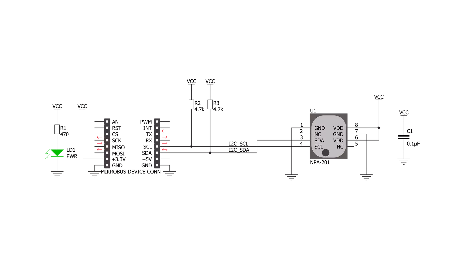
Altitude 4 Click is based on the NPA-201 , a digital output absolute pressure sensor that provides low power consumption and compact size. With a miniature 2.0x2.5x1.0mm HCLGA package, it is ideally suited for portable electronics and space-constrained applications. Low power consumption of 20nA during Sleep Mode is ideal for battery and other low-power applications. A wide operating temperature range from -40°C to +85°C fits well with demanding environmental requirements. Equipped with a MEMS pressure sensor with a signal-conditioning IC, Click Board™ provides accurate measurements from 260 to 1260 mBar. Thanks to ASIC's inner structure, the measurement results are not only compensated but also temperature corrected and calibrated
with an internal sensor. Digital compensation of the signal offset, sensitivity, temperature and non-linearity is accomplished via an 18-bit internal digital signal processor (DSP) running a correction algorithm. Calibration coefficients are stored on-chip in highly reliable, nonvolatile, multiple-time programmable (MTP) memory. The measurement and corrected bridge values provided at the digital output of the chip are routed to Mikrobus I2C reserved pins SCL and SDA. This device offers the possibility to change the I2C slave address. NPA-201 sensors are supplied with the slave address set to default value. This address is stored within the sensor's internal EEPROM memory. By modifying the specific bits, the sensor is put into a special programming mode following the instruction sent
by the master in order to change the slave address. Before attempting this procedure, users should familiarise themselves with the datasheet provided by the manufacturer. Care must be taken to ensure that only the specified data bits are changed. Writing data to other locations may cause the sensor to become permanently unusable. The address can be changed up to 3 times, after which no further memory changes are possible. This Click Board™ uses the I2C communication interface and is designed to be operated only with a 3.3V logic level. A proper logic voltage level conversion should be performed before the Click board™ is used with MCUs with different logic levels.


Features overview
Development board
PIC32MZ Clicker is a compact starter development board that brings the flexibility of add-on Click boards™ to your favorite microcontroller, making it a perfect starter kit for implementing your ideas. It comes with an onboard 32-bit PIC32MZ microcontroller with FPU from Microchip, a USB connector, LED indicators, buttons, a mikroProg connector, and a header for interfacing with external electronics. Thanks to its compact design with clear and easy-recognizable silkscreen markings, it provides a fluid and immersive working experience, allowing access anywhere and under
any circumstances. Each part of the PIC32MZ Clicker development kit contains the components necessary for the most efficient operation of the same board. In addition to the possibility of choosing the PIC32MZ Clicker programming method, using USB HID mikroBootloader, or through an external mikroProg connector for PIC, dsPIC, or PIC32 programmer, the Clicker board also includes a clean and regulated power supply module for the development kit. The USB Micro-B connection can provide up to 500mA of current, which is more than enough to operate all onboard
and additional modules. All communication methods that mikroBUS™ itself supports are on this board, including the well-established mikroBUS™ socket, reset button, and several buttons and LED indicators. PIC32MZ Clicker is an integral part of the Mikroe ecosystem, allowing you to create a new application in minutes. Natively supported by Mikroe software tools, it covers many aspects of prototyping thanks to a considerable number of different Click boards™ (over a thousand boards), the number of which is growing every day.

Microcontroller Overview
MCU Card / MCU

Architecture
PIC32
MCU Memory (KB)
1024
Silicon Vendor
Microchip
Pin count
64
RAM (Bytes)
524288
Used MCU Pins
mikroBUS™ mapper
Take a closer look
Click board™ Schematic
Step by step
Project assembly

Start by selecting your development board and Click board™. Begin with the PIC32MZ clicker as your development board.


Software Support
Library Description
This library contains API for Altitude 4 Click driver.
Key functions:
altitude4_generic_read- This function stores the len amount of data into the r_buf. The data is read from the address regaltitude4_generic_write- This function writes the len amount of data from the w_buf to the address regaltitude4_read_sensor- This function acquires sensor data from the click module and stores it in the sensor data object
Open Source
Code example
The complete application code and a ready-to-use project are available through the NECTO Studio Package Manager for direct installation in the NECTO Studio. The application code can also be found on the MIKROE GitHub account.
/*!
 * \file
 * \brief Altitude4 Click example
 *
 * # Description
 * This example showcases how to initialize, configure and use the Altitude 4 Click module. The
 * Click has a sensor that measures: altitude, pressure and temperature. No additional equipment
 * or special configuration is required in order for this demo to work.
 *
 * The demo application is composed of two sections :
 *
 * ## Application Init
 * This function initializes and configures the logger and Click modules.
 *
 * ## Application Task
 * This function initializes the sensor data object through the read_sensor(...) function and
 * then prints altitude, pressure and temperature values in the UART console. It does so every
 * second.
 *
 * \author MikroE Team
 *
 */
// ------------------------------------------------------------------- INCLUDES

#include "board.h"
#include "log.h"
#include "altitude4.h"

// ------------------------------------------------------------------ VARIABLES

static altitude4_t altitude4;
static log_t logger;

// ------------------------------------------------------ APPLICATION FUNCTIONS

void application_init ( void )
{
    log_cfg_t log_cfg;
    altitude4_cfg_t cfg;

    /**
     * Logger initialization.
     * Default baud rate: 115200
     * Default log level: LOG_LEVEL_DEBUG
     * @note If USB_UART_RX and USB_UART_TX
     * are defined as HAL_PIN_NC, you will
     * need to define them manually for log to work.
     * See @b LOG_MAP_USB_UART macro definition for detailed explanation.
     */
    LOG_MAP_USB_UART( log_cfg );
    log_init( &logger, &log_cfg );
    log_info( &logger, "---- Application Init ----" );

    //  Click initialization.

    altitude4_cfg_setup( &cfg );
    ALTITUDE4_MAP_MIKROBUS( cfg, MIKROBUS_1 );
    altitude4_init( &altitude4, &cfg );
    Delay_ms ( 500 );
}

void application_task ( void )
{
    altitude4_sensor_t sensor_data;

    altitude4_read_sensor( &altitude4, &sensor_data );

    log_printf( &logger, " * Altitude: %.2f m\r\n", sensor_data.altitude );
    log_printf( &logger, " * Pressure: %.2f mBar\r\n", sensor_data.pressure );
    log_printf( &logger, " * Temperature: %.2f C\r\n", sensor_data.temperature );
    log_printf( &logger, " -------------------------\r\n" );

    Delay_1sec( );
}

int main ( void )
{
    /* Do not remove this line or clock might not be set correctly. */
    #ifdef PREINIT_SUPPORTED
    preinit();
    #endif

    application_init( );

    for ( ; ; )
    {
        application_task( );
    }

    return 0;
}

// ------------------------------------------------------------------------ END


