Optimize BLDC control with TC78B042FTG and PIC32MZ1024EFH064
Navigate with precision and ease

Published Jul 26, 2023
Click board™
Brushless 8 Click
Dev. board
PIC32MZ clicker
Compiler
NECTO Studio
MCU
PIC32MZ1024EFH064
Drive industrial equipment with advanced brushless motor control. Act now and revolutionize your engineering project
A
A
Hardware Overview
How does it work?
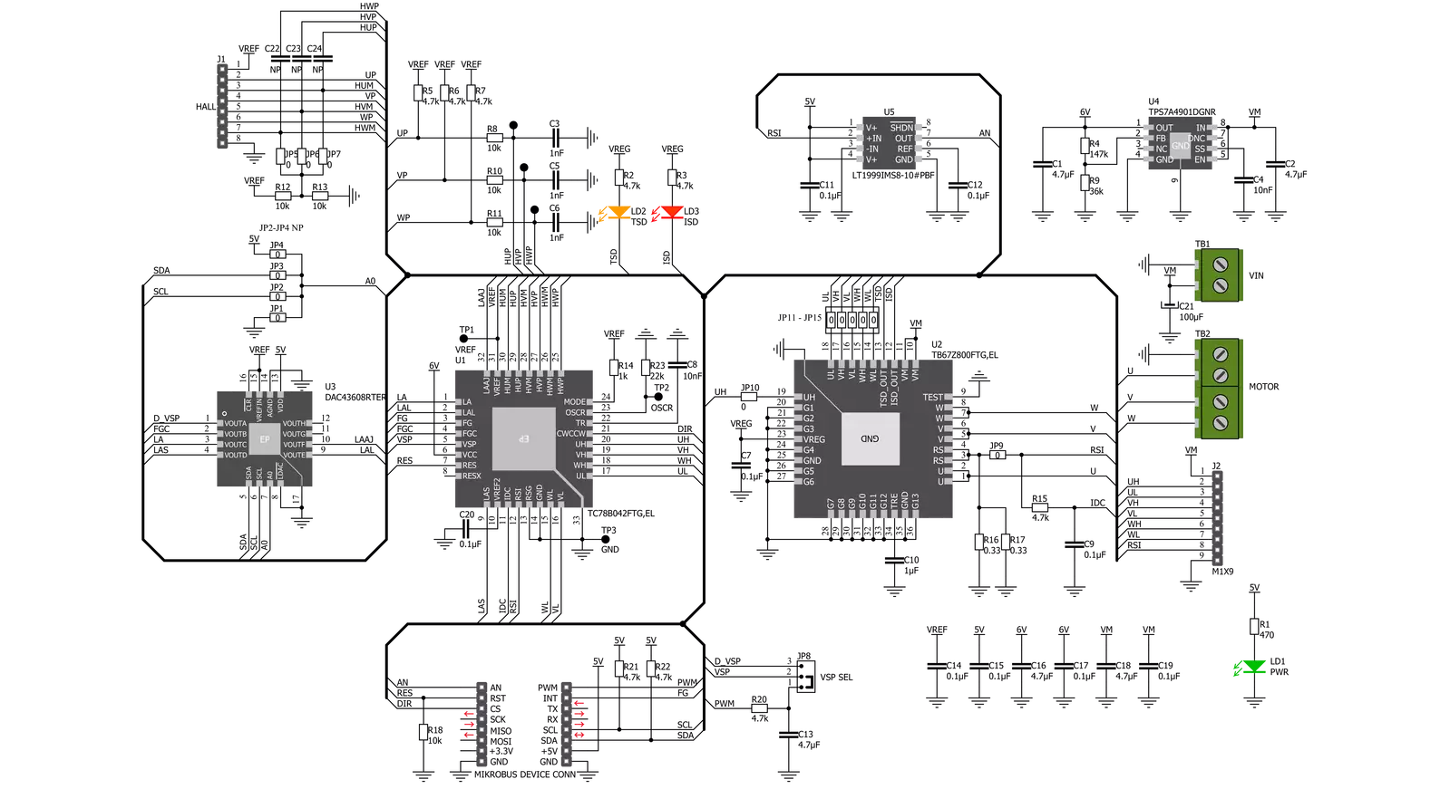
Brushless 8 Click is based on the TC78B042FTG, a three-phase brushless motor controller that offers high efficiency over a wide rotation range with automatic phase adjustment from Toshiba Semiconductor. This motor controller incorporates Toshiba’s originally developed Intelligent Phase Control that secures high-level efficiency for a wide range of rotation speeds. As a result, the new devices can be used with motor drivers with various voltages and current capacities and in combination with intelligent power devices at the output stages. It uses a sine-wave drive system with a smooth current waveform that reduces noise and generates less noise and vibration than motors with a rectangular wave drive system. This Click board™ also contains a 3-channel Half-Bridge driver inverter, TB67Z800FTG from Toshiba Semiconductor, that receives its high and low side gate drive signals from TC78B042FTG and runs the connected Brushless DC Motor up to 22V/3A. For this type of application, more precisely for Brushless Click boards that require BLDC Motor with Hall Sensor for their work, Mikroe offers its users just one such motor, whose offer you can find in our shop. The typical oscillation frequency is 9.22 MHz based on resistor R23 value 22kΩ drives
the motor with 120° commutation. When the Hall signal indicates a rotation speed of 1 Hz or more, the motor rotates by estimating the rotor position according to the command of the LA pin. When the rotation speed is less than 1Hz, or the motor rotation direction is reversed, the motor is driven with 120° commutation. The desired value on the previously mentioned LA pin as well as on other pins related to lead angle control, the TC78B042FTG, obtains by the DAC3608, a low-power, eight-channel, digital-to-analog converter from Texas Instruments, which establishes communication with MCU via I2C serial communication. Besides, the DAC43608 also allows the user to select a valid I2C address byte between 5V, GND, or I2C communication lines by positioning the jumper to an appropriate position marked from JP1 to JP4. As for the TC78B042FTG power supply, it is powered with a voltage value obtained by TPS7A49, an ultralow-noise linear regulator from Texas Instruments that converts an input value in the range of 6.5 to 22V to 6V that powers the main chip. In addition to I2C communication, several GPIO pins connected to the mikroBUS™ socket pins are also used. The DIR pin, routed on the CS pin of the mikroBUS™
socket, is used while the control of the motor rotation speed itself can be to select the direction of motor rotation, chosen via the VSP SEL jumper. With this jumper, the user can rotate speed control using a PWM signal or a value obtained by the DAC43608. The pin marked with RES routed at the RST pin of the mikroBUS™ socket can be used for Error detection, more precisely for turning commutation outputs on or off. The FG pin at the INT pin of the mikroBUS™ socket represents the rotating pulse based on the selectable number of pulses per revolution. And the last pin labeled as AN provides accurate, current monitoring via LT1999-10, a high-voltage, bidirectional current sense amplifier from Analog Devices. Two headers on the board contain both W, V and U-phase Hall input signals and a header with High & Low-side commutation signals. Besides, it has 2 LED indicators labeled ISD and TSD intended for thermal shutdown and over-current protection. This Click board™ is designed to be operated only with a 5V logic voltage level. A proper logic voltage level conversion should be performed before the Click board™ is used with MCUs with different logic levels.

Features overview
Development board
PIC32MZ Clicker is a compact starter development board that brings the flexibility of add-on Click boards™ to your favorite microcontroller, making it a perfect starter kit for implementing your ideas. It comes with an onboard 32-bit PIC32MZ microcontroller with FPU from Microchip, a USB connector, LED indicators, buttons, a mikroProg connector, and a header for interfacing with external electronics. Thanks to its compact design with clear and easy-recognizable silkscreen markings, it provides a fluid and immersive working experience, allowing access anywhere and under
any circumstances. Each part of the PIC32MZ Clicker development kit contains the components necessary for the most efficient operation of the same board. In addition to the possibility of choosing the PIC32MZ Clicker programming method, using USB HID mikroBootloader, or through an external mikroProg connector for PIC, dsPIC, or PIC32 programmer, the Clicker board also includes a clean and regulated power supply module for the development kit. The USB Micro-B connection can provide up to 500mA of current, which is more than enough to operate all onboard
and additional modules. All communication methods that mikroBUS™ itself supports are on this board, including the well-established mikroBUS™ socket, reset button, and several buttons and LED indicators. PIC32MZ Clicker is an integral part of the Mikroe ecosystem, allowing you to create a new application in minutes. Natively supported by Mikroe software tools, it covers many aspects of prototyping thanks to a considerable number of different Click boards™ (over a thousand boards), the number of which is growing every day.

Microcontroller Overview
MCU Card / MCU

Architecture
PIC32
MCU Memory (KB)
1024
Silicon Vendor
Microchip
Pin count
64
RAM (Bytes)
524288
You complete me!
Accessories
Brushless DC (BLDC) Motor with a Hall sensor represents a high-performance motor from the 42BLF motor series. This motor, wired in a star configuration, boasts a Hall Effect angle of 120°, ensuring precise and reliable performance. With a compact motor length of 47mm and a lightweight design tipping the scales at just 0.29kg, this BLDC motor is engineered to meet your needs. Operating flawlessly at a voltage rating of 24VDC and a speed range of 4000 ± 10% RPM, this motor offers consistent and dependable power. It excels in a normal operational temperature range from -20 to +50°C, maintaining efficiency with a rated current of 1.9A. Also, this product seamlessly integrates with all Brushless Click boards™ and those that require BLDC motors with Hall sensors.

Used MCU Pins
mikroBUS™ mapper
Take a closer look
Click board™ Schematic
Step by step
Project assembly

Start by selecting your development board and Click board™. Begin with the PIC32MZ clicker as your development board.


Track your results in real time
Application Output
1. Application Output - In Debug mode, the 'Application Output' window enables real-time data monitoring, offering direct insight into execution results. Ensure proper data display by configuring the environment correctly using the provided tutorial.

2. UART Terminal - Use the UART Terminal to monitor data transmission via a USB to UART converter, allowing direct communication between the Click board™ and your development system. Configure the baud rate and other serial settings according to your project's requirements to ensure proper functionality. For step-by-step setup instructions, refer to the provided tutorial.

3. Plot Output - The Plot feature offers a powerful way to visualize real-time sensor data, enabling trend analysis, debugging, and comparison of multiple data points. To set it up correctly, follow the provided tutorial, which includes a step-by-step example of using the Plot feature to display Click board™ readings. To use the Plot feature in your code, use the function: plot(*insert_graph_name*, variable_name);. This is a general format, and it is up to the user to replace 'insert_graph_name' with the actual graph name and 'variable_name' with the parameter to be displayed.

Software Support
Library Description
This library contains API for Brushless 8 Click driver.
Key functions:
brushless8_cfg_setup- This function initializes click configuration structure to initial valuesbrushless8_init- This function initializes all necessary pins and peripherals used for Brushless 8 Clickbrushless8_default_cfg- This function executes a default configuration of Brushless 8 Click
Open Source
Code example
The complete application code and a ready-to-use project are available through the NECTO Studio Package Manager for direct installation in the NECTO Studio. The application code can also be found on the MIKROE GitHub account.
/*!
 * @file main.c
 * @brief Brushless8 Click example
 *
 * # Description
 * This example showcases how to initialize and use the Brushless 8 click.
 * This application is a schowcase of controlling speed
 * and direction of brushless motor with hall sesnor.
 *
 * The demo application is composed of two sections :
 *
 * ## Application Init
 * Initializes the click board to appropriate settings based on selected mode.
 * Initialization settings are sent through I2C bus and the motor itself is
 * controlled via PWM or DAC over I2C.
 * Modes:
 *     - BRUSHLESS8_PWM
 *     - BRUSHLESS8_DAC
 *
 * ## Application Task
 * This example demonstrates the use of Brushless 8 click board.
 * Brushless 8 click communicates with the device via I2C driver in order to
 * set adequate voltage level for connected motor.
 * Current PWM/DAC settings being output are sent via logger.
 * Results are being sent to the Usart Terminal where you can track their changes.
 *
 * @note Take into consideration that the jumper on Brushless 8 click board
 * has to be set adequately for selected mode ( @b VSPSEL ).
 *
 * @author Nikola Peric
 */

// ------------------------------------------------------------------- INCLUDES

#include "brushless8.h"
#include "board.h"
#include "math.h"
#include "log.h"

/* Select desired mode. */
#define BRUSHLESS8_MODE BRUSHLESS8_PWM

#define COMM_DELAY 500

// ------------------------------------------------------------------ VARIABLES

static brushless8_t brushless8;
static log_t logger;

// ------------------------------------------------------ APPLICATION FUNCTIONS

void application_init ( void )
{
    log_cfg_t log_cfg;  /**< Logger config object. */
    brushless8_cfg_t brushless8_cfg;  /**< Click config object. */

    /**
     * Logger initialization.
     * Default baud rate: 115200
     * Default log level: LOG_LEVEL_DEBUG
     * @note If USB_UART_RX and USB_UART_TX
     * are defined as HAL_PIN_NC, you will
     * need to define them manually for log to work.
     * See @b LOG_MAP_USB_UART macro definition for detailed explanation.
     */
    LOG_MAP_USB_UART( log_cfg );
    log_init( &logger, &log_cfg );
    log_info( &logger, "Application Init" );

    // Click initialization.

    brushless8_cfg_setup( &brushless8_cfg );
    // Select desired mode.
    brushless8_cfg.ctrl_mod = BRUSHLESS8_MODE;
    BRUSHLESS8_MAP_MIKROBUS( brushless8_cfg, MIKROBUS_1 );

    BRUSHLESS8_RETVAL init_flag = brushless8_init( &brushless8, &brushless8_cfg );
    if ( BRUSHLESS8_OK != init_flag )
    {
        log_error( &logger, "Application Init Error" );
        log_info( &logger, "Please, run program again..." );

        for ( ; ; );
    }

    brushless8_default_cfg ( &brushless8 );

    if ( BRUSHLESS8_PWM == brushless8.ctrl_mod )
    {
        brushless8_set_dac_vout( &brushless8, BRUSHLESS8_DAC_REG_CHN_A_DVSP, 0 );
        brushless8_set_duty_cycle( &brushless8, 0 );
        brushless8_pwm_start( &brushless8 );

        Delay_ms( 3000 );
    }

    log_info( &logger, "Application Task" );
    log_printf( &logger, "------------------------------\r\n" );
}

void application_task ( void )
{
    static int8_t duty_cnt = 1;
    static int8_t duty_inc = 1;
    float duty = duty_cnt / 10.0;

    brushless8_set_duty_cycle ( &brushless8, duty );
    log_printf( &logger, "> Duty: %d%%\r\n", ( uint16_t )( duty_cnt * 10 ) );

    Delay_ms( 500 );

    if ( 10 == duty_cnt )
    {
        duty_inc = -1;
    }
    else if ( 0 == duty_cnt )
    {
        duty_inc = 1;
    }
    duty_cnt += duty_inc;
}

void main ( void )
{
    application_init( );

    for ( ; ; )
    {
        application_task( );
    }
}

// ------------------------------------------------------------------------ END


