Experience the art of signal convergence with TMUX1208 and PIC32MZ1024EFH064
Where signals converge, choices expand!

Published Aug 18, 2023
Click board™
MUX 3 Click
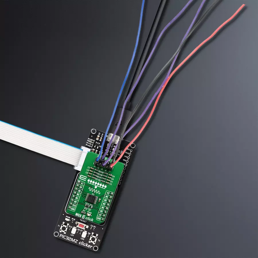
Dev. board
PIC32MZ clicker
Compiler
NECTO Studio
MCU
PIC32MZ1024EFH064
Crafted for versatility and precision, our general-purpose CMOS multiplexer empowers you to effortlessly manage and direct various signals, expanding your options for seamless connectivity
A
A
Hardware Overview
How does it work?
MUX 3 Click is based on the TMUX1208, a 5-V Bidirectional 8:1, 1-Channel Multiplexer from Texas Instruments. The TMUX1208 is a general-purpose complementary metal-oxide semiconductor (CMOS) multiplexer (MUX). A wide operating supply of 1.08 V to 5.5 V allows use in various applications, from personal electronics to building automation applications. The device supports bidirectional analog and digital signals on the source (Sx) and drain (D) pins ranging from GND to VDD. All logic inputs have 1.8 V logic-compatible thresholds, ensuring TTL and CMOS logic compatibility when operating in the valid supply voltage range. Fail-Safe Logic circuitry allows voltages on the control pins to be applied before the supply pin, protecting the device from
potential damage. Break-before-make delay is a safety feature that prevents two inputs from connecting when switching devices. The output first breaks from the on-state switch before making the connection with the next on-state switch. The time delay between the break and the make is known as the break-before-make delay. One useful application for the TMUX1208 features is multiplexing various signals into an ADC integrated into an MCU. Utilizing an integrated ADC in the MCU allows a system to minimize cost with a potential tradeoff of system performance when compared to an external ADC. The multiplexer allows for multiple inputs/sensors to be monitored with a single ADC pin of the device, which is critical in systems with limited I/O. Given
all the features the TMUX1208 offers, the MUX 3 Click is best used for Analog and Digital Multiplexing / Demultiplexing, HVAC: Heating, Ventilation, and Air Conditioning, Smoke Detectors, Video Surveillance, Electronic Point of Sale, Battery-Powered Equipment, Appliances, Consumer Audio. This Click board™ can operate with either 3.3V or 5V logic voltage levels selected via the VCC SEL jumper. This way, both 3.3V and 5V capable MCUs can use the communication lines properly. Also, this Click board™ comes equipped with a library containing easy-to-use functions and an example code that can be used, as a reference, for further development.


Features overview
Development board
PIC32MZ Clicker is a compact starter development board that brings the flexibility of add-on Click boards™ to your favorite microcontroller, making it a perfect starter kit for implementing your ideas. It comes with an onboard 32-bit PIC32MZ microcontroller with FPU from Microchip, a USB connector, LED indicators, buttons, a mikroProg connector, and a header for interfacing with external electronics. Thanks to its compact design with clear and easy-recognizable silkscreen markings, it provides a fluid and immersive working experience, allowing access anywhere and under
any circumstances. Each part of the PIC32MZ Clicker development kit contains the components necessary for the most efficient operation of the same board. In addition to the possibility of choosing the PIC32MZ Clicker programming method, using USB HID mikroBootloader, or through an external mikroProg connector for PIC, dsPIC, or PIC32 programmer, the Clicker board also includes a clean and regulated power supply module for the development kit. The USB Micro-B connection can provide up to 500mA of current, which is more than enough to operate all onboard
and additional modules. All communication methods that mikroBUS™ itself supports are on this board, including the well-established mikroBUS™ socket, reset button, and several buttons and LED indicators. PIC32MZ Clicker is an integral part of the Mikroe ecosystem, allowing you to create a new application in minutes. Natively supported by Mikroe software tools, it covers many aspects of prototyping thanks to a considerable number of different Click boards™ (over a thousand boards), the number of which is growing every day.

Microcontroller Overview
MCU Card / MCU

Architecture
PIC32
MCU Memory (KB)
1024
Silicon Vendor
Microchip
Pin count
64
RAM (Bytes)
524288
Used MCU Pins
mikroBUS™ mapper
Take a closer look
Click board™ Schematic

Step by step
Project assembly

Start by selecting your development board and Click board™. Begin with the PIC32MZ clicker as your development board.


Software Support
Library Description
This library contains API for MUX 3 Click driver.
Key functions:
mux3_set_channel- Set active MUX channel function
Open Source
Code example
The complete application code and a ready-to-use project are available through the NECTO Studio Package Manager for direct installation in the NECTO Studio. The application code can also be found on the MIKROE GitHub account.
/*!
 * \file
 * \brief MUX 3 Click example
 *
 * # Description
 * This application sets multiplexing one input channel to eight single-ended output channels.
 *
 * The demo application is composed of two sections :
 *
 * ## Application Init
 * Initialization driver enable's - GPIO, also write log.
 *
 * ## Application Task
 * This is an example which demonstrates the use of MUX 3 Click board.
 * Sets the current active and changes the channel every 1 sec.
 * Results are being sent to the Usart Terminal where you can track their changes.
 * All data logs write on Usart Terminal changes for every 1 sec.
 *
 * \author MikroE Team
 *
 */
// ------------------------------------------------------------------- INCLUDES

#include "board.h"
#include "log.h"
#include "mux3.h"

// ------------------------------------------------------------------ VARIABLES

static mux3_t mux3;
static log_t logger;

// ------------------------------------------------------ APPLICATION FUNCTIONS

void application_init ( void )
{
    log_cfg_t log_cfg;
    mux3_cfg_t cfg;

    /**
     * Logger initialization.
     * Default baud rate: 115200
     * Default log level: LOG_LEVEL_DEBUG
     * @note If USB_UART_RX and USB_UART_TX
     * are defined as HAL_PIN_NC, you will
     * need to define them manually for log to work.
     * See @b LOG_MAP_USB_UART macro definition for detailed explanation.
     */
    LOG_MAP_USB_UART( log_cfg );
    log_init( &logger, &log_cfg );
    log_info(&logger, "---- Application Init ----");

    //  Click initialization.

    mux3_cfg_setup( &cfg );
    MUX3_MAP_MIKROBUS( cfg, MIKROBUS_1 );
    mux3_init( &mux3, &cfg );
}

void application_task ( void )
{
    mux3_set_channel( &mux3, MUX3_ENABLE_CHANNEL_S1 );
    log_printf( &logger, "Active channel: S1\r\n" );
    Delay_1sec( );

    mux3_set_channel( &mux3, MUX3_ENABLE_CHANNEL_S2 );
    log_printf( &logger, "Active channel: S2\r\n" );
    Delay_1sec( );

    mux3_set_channel( &mux3, MUX3_ENABLE_CHANNEL_S3 );
    log_printf( &logger, "Active channel: S3\r\n" );
    Delay_1sec( );

    mux3_set_channel( &mux3, MUX3_ENABLE_CHANNEL_S4 );
    log_printf( &logger, "Active channel: S4\r\n" );
    Delay_1sec( );

    mux3_set_channel( &mux3, MUX3_ENABLE_CHANNEL_S5 );
    log_printf( &logger, "Active channel: S5\r\n" );
    Delay_1sec( );

    mux3_set_channel( &mux3, MUX3_ENABLE_CHANNEL_S6 );
    log_printf( &logger, "Active channel: S6\r\n" );
    Delay_1sec( );

    mux3_set_channel( &mux3, MUX3_ENABLE_CHANNEL_S7 );
    log_printf( &logger, "Active channel: S7\r\n" );
    Delay_1sec( );

    mux3_set_channel( &mux3, MUX3_ENABLE_CHANNEL_S8 );
    log_printf( &logger, "Active channel: S8\r\n" );
    Delay_1sec( );

    mux3_set_channel( &mux3, MUX3_DISABLE_ALL_CHANNELS );
    log_printf( &logger, "Active channel: none\r\n" );
    log_printf( &logger, "-------------------\r\n" );
    Delay_1sec( );
}

int main ( void )
{
    /* Do not remove this line or clock might not be set correctly. */
    #ifdef PREINIT_SUPPORTED
    preinit();
    #endif

    application_init( );

    for ( ; ; )
    {
        application_task( );
    }

    return 0;
}

// ------------------------------------------------------------------------ END


