Integrate dual-mode Bluetooth (BR/EDR and LE) wireless capabilities into your projects with BM78 and PIC18F87J50
Fully certified 2.4GHz Bluetooth Classic (BR/EDR) and Bluetooth Low Energy (LE) wireless solution

Published Aug 05, 2024
Click board™
BM78 Click
Dev. board
Clicker 2 for PIC18FJ
Compiler
NECTO Studio
MCU
PIC18F87J50
Enable dual-mode Bluetooth wireless connectivity for IoT, secure payment systems, home automation, and industrial applications
A
A
Hardware Overview
How does it work?
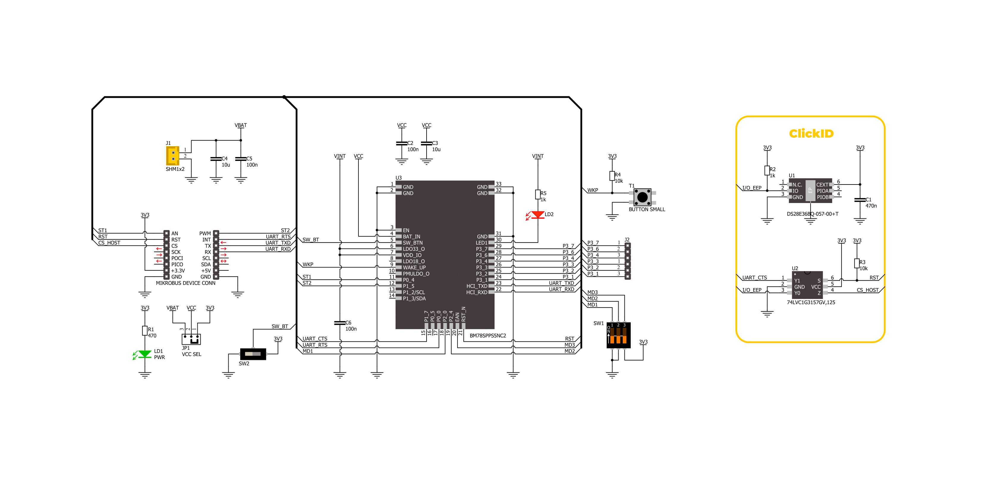
BM78 Click is based on the BM78, a fully certified 2.4GHz Bluetooth (BR/EDR/LE) wireless module from Microchip. It is designed to integrate dual-mode Bluetooth wireless capability into various projects easily. The BM78 is built around Microchip's IS1678 Bluetooth Dual mode SoC, specifically the ROM-based BM78SPPX5NC2 version. The module includes an on-board Bluetooth stack, power management subsystem, 2.4GHz transceiver, and RF power amplifier. It supports GAP, SDP, SPP, and GATT profiles, enabling data transfer through transparent UART mode for easy integration with any MCU with a UART interface. This makes it ideal for connecting products to smartphones or tablets for convenient data transfer, control, cloud application access, and local connectivity for IoT, secure payment systems, home automation, security, industrial applications, and data logging. BM78 Click provides flexibility with two operational modes: Auto-Pattern and Manual-Pattern. These modes use different state machines and can be selected by setting the appropriate value in the EEPROM memory. By
default, the BM78 module operates in Auto-Pattern mode. The board also includes a MODE SEL switch that allows users to set the module in one of two modes: application mode for normal operation or test mode to change EEPROM values. The module operates normally when all three switches are in the HIGH position. The module enters test mode if only the first switch (1) is in the LOW position. As mentioned, communication between the BM78 and the host MCU is made through a UART interface, standard UART RX and TX pins, and hardware flow control pins (CTS and RTS) for efficient data transfer. The BM78 Click also features a reset (RST) pin for hard resetting the module and two status indicators on the ST1 and ST2 pins. These pins provide various status indications to the host MCU, such as Power-On, deep state, access state, and link state indications, showing whether UART data is being transmitted or not. In addition, this board also includes a SW BT switch, which acts as a software power button, allowing the user to power the BM78 module ON (high) or switch it OFF (low) into Deep Sleep mode to reduce power
consumption. Also, the board features a WAKE button, which transitions the module from Sleep mode to Standby mode, a user-configurable red LED indicator labeled LD2, which indicates various statuses such as standby, link back, low battery, inquiry, or link, and two unpopulated 1x3 headers that provide access to several I/O pins of the BM78. These pins can perform multiple functions, including low battery indication, RSSI, link drop, UART RX, pairing key, and inquiry control, among others. This Click board™, and the module itself, can be operated only with a 3.3V logic voltage level. For this reason, in addition to being powered via a mikroBUS™ socket, users can also opt for external battery power, with power selection managed through the VCC SEL jumper. The board must perform appropriate logic voltage level conversion before using MCUs with different logic levels. Also, it comes equipped with a library containing functions and an example code that can be used as a reference for further development.

Features overview
Development board
Clicker 2 for PIC18FJ is a compact starter development board that brings the flexibility of add-on Click boards™ to your favorite microcontroller, making it a perfect starter kit for implementing your ideas. It comes with an onboard 8-bit PIC microcontroller, the PIC18F87J50 from Microchip, two mikroBUS™ sockets for Click board™connectivity, a USB connector, LED indicators, buttons, a mikroProg connector, and two 26-pin headers for interfacing with external electronics. Its compact design with clear and easily recognizable silkscreen markings allows you to build gadgets with unique functionalities and features quickly. Each part of the Clicker 2 for
PIC18FJ development kit contains the components necessary for the most efficient operation of the same board. In addition to the possibility of choosing the Clicker 2 for PIC18FJ programming method: using USB HID mikroBootloader, an external mikroProg connector for PIC18FJ programmer, or through an external ICD3/3 programmer, the Clicker 2 board also includes a clean and regulated power supply module for the development kit. It provides two ways of board-powering; through the USB Mini-B cable, where onboard voltage regulators provide the appropriate voltage levels to each component on the board or using a Li-Polymer battery via an onboard battery
connector. All communication methods that mikroBUS™ itself supports are on this board, including the well-established mikroBUS™ socket, reset button, and several user-configurable buttons and LED indicators. Clicker 2 for PIC18FJ is an integral part of the Mikroe ecosystem, allowing you to create a new application in minutes. Natively supported by Mikroe software tools, it covers many aspects of prototyping thanks to a considerable number of different Click boards™ (over a thousand boards), the number of which is growing every day.

Microcontroller Overview
MCU Card / MCU
Architecture
PIC
MCU Memory (KB)
128
Silicon Vendor
Microchip
Pin count
80
RAM (Bytes)
3904
Used MCU Pins
mikroBUS™ mapper
Take a closer look
Click board™ Schematic
Step by step
Project assembly

Start by selecting your development board and Click board™. Begin with the Clicker 2 for PIC18FJ as your development board.


Software Support
Library Description
This library contains API for BM78 Click driver.
Key functions:
bm78_eeprom_send_cmd- This function is used to send specific EEPROM command by using UART serial interface.bm78_eeprom_write- This function is used to write data into the EEPROM location specified by the address parameter.bm78_flash_eeprom- This function is used write default configuration into the EEPROM.
Open Source
Code example
The complete application code and a ready-to-use project are available through the NECTO Studio Package Manager for direct installation in the NECTO Studio. The application code can also be found on the MIKROE GitHub account.
/*!
 * @file main.c
 * @brief BM78 Click Example.
 *
 * # Description
 * This example demonstrates the use of BM78 Click board by processing
 * the incoming data and displaying them on the USB UART.
 *
 * The demo application is composed of two sections :
 *
 * ## Application Init
 * Initializes the driver and performs the Click default configuration by writing it into the EEPROM.
 *
 * ## Application Task
 * Reads and processes all incoming data from the Serial Bluetooth Terminal smartphone application and displays them on the USB UART.
 *
 * ## Additional Function
 * - static void bm78_clear_app_buf ( void )
 * - static void bm78_log_app_buf ( void )
 * - static err_t bm78_process ( bm78_t *ctx )
 *
 * @note
 * We have used the Serial Bluetooth Terminal smartphone application for the test.
 * A smartphone and the Click board must be paired in order to exchange messages with each other.
 *
 * @author Stefan Ilic
 *
 */

#include "board.h"
#include "log.h"
#include "bm78.h"

// Application buffer size
#define APP_BUFFER_SIZE             500
#define PROCESS_BUFFER_SIZE         200

static bm78_t bm78;
static log_t logger;

static uint8_t app_buf[ APP_BUFFER_SIZE ] = { 0 };
static int32_t app_buf_len = 0;

/**
 * @brief BM78 clearing application buffer.
 * @details This function clears memory of application buffer and reset its length.
 * @note None.
 */
static void bm78_clear_app_buf ( void );

/**
 * @brief BM78 log application buffer.
 * @details This function logs data from application buffer to USB UART.
 * @note None.
 */
static void bm78_log_app_buf ( void );

/**
 * @brief BM78 data reading function.
 * @details This function reads data from device and concatenates data to application buffer.
 * @param[in] ctx : Click context object.
 * See #bm78_t object definition for detailed explanation.
 * @return @li @c  0 - Read some data.
 *         @li @c -1 - Nothing is read.
 * See #err_t definition for detailed explanation.
 * @note None.
 */
static err_t bm78_process ( bm78_t *ctx );

void application_init ( void )
{
    log_cfg_t log_cfg;  /**< Logger config object. */
    bm78_cfg_t bm78_cfg;  /**< Click config object. */

    /**
     * Logger initialization.
     * Default baud rate: 115200
     * Default log level: LOG_LEVEL_DEBUG
     * @note If USB_UART_RX and USB_UART_TX
     * are defined as HAL_PIN_NC, you will
     * need to define them manually for log to work.
     * See @b LOG_MAP_USB_UART macro definition for detailed explanation.
     */
    LOG_MAP_USB_UART( log_cfg );
    log_init( &logger, &log_cfg );
    log_info( &logger, " Application Init " );

    // Click initialization.
    bm78_cfg_setup( &bm78_cfg );
    BM78_MAP_MIKROBUS( bm78_cfg, MIKROBUS_1 );
    if ( UART_ERROR == bm78_init( &bm78, &bm78_cfg ) )
    {
        log_error( &logger, " Communication init." );
        for ( ; ; );
    }
    uint8_t tmp_data[ 16 ];
    bm78_generic_read( &bm78, &tmp_data, 1 );
    Delay_ms ( 100 );

    log_printf( &logger, " = = = = = = = = = = = = = = = = = \r\n" );
    log_printf( &logger, " Place Click into Write EEPROM mode \r\n" );
    log_printf( &logger, " By setting MODE SEL in the following configuration \r\n" );
    log_printf( &logger, "         | 1 | 2 | 3 |             \r\n" );
    log_printf( &logger, "         | H | L | L |             \r\n" );
    log_printf( &logger, " = = = = = = = = = = = = = = = = = \r\n" );
    log_printf( &logger, " Send YES once you placed Click into Write EEPROM mode \r\n" );
    #define WANTED_ANSWER "YES/r/n"
    log_printf( &logger, " = = = = = = = = = = = = = = = = = \r\n" );
    while ( 1 )
    {
        log_read( &logger, &tmp_data, 5 );

        if ( 0 == strstr ( WANTED_ANSWER, tmp_data ) )
        {
            break;
        }
        else
        {
            log_printf( &logger, " Send YES once you placed Click into Write EEPROM mode \r\n" );
        }
    }
    bm78_hw_reset( &bm78 );
    log_printf( &logger, " Writing into the EEPROM \r\n" );
    if ( BM78_ERROR == bm78_flash_eeprom ( &bm78 ) )
    {
        log_error( &logger, " EEPROM Flash failed. " );
        log_printf( &logger, " Check Selected Click mode. \r\n" );
        for ( ; ; );
    }

    log_printf( &logger, " = = = = = = = = = = = = = = = = = \r\n" );
    log_printf( &logger, " Place Click into Application mode \r\n" );
    log_printf( &logger, " By setting MODE SEL in the following configuration \r\n" );
    log_printf( &logger, "         | 1 | 2 | 3 |             \r\n" );
    log_printf( &logger, "         | L | L | L |             \r\n" );
    log_printf( &logger, " = = = = = = = = = = = = = = = = = \r\n" );
    log_printf( &logger, " Send YES once you placed Click into Application mode \r\n" );
    log_printf( &logger, " = = = = = = = = = = = = = = = = = \r\n" );
    while ( 1 )
    {
        log_read( &logger, &tmp_data, 5 );

        if ( 0 == strstr ( WANTED_ANSWER, tmp_data ) )
        {
            break;
        }
        else
        {
            log_printf( &logger, " Send YES once you placed Click into Application mode \r\n" );
        }
    }
    bm78_hw_reset( &bm78 );

    log_info( &logger, " Application Task " );
    log_printf( &logger, " Connect to the device using the Serial Bluetooth Terminal App \r\n\r\n" );
}

void application_task ( void )
{
    if ( BM78_OK == bm78_process( &bm78 ) )
    {
        bm78_log_app_buf( );
        bm78_clear_app_buf( );
    }
}

int main ( void )
{
    /* Do not remove this line or clock might not be set correctly. */
    #ifdef PREINIT_SUPPORTED
    preinit();
    #endif

    application_init( );

    for ( ; ; )
    {
        application_task( );
    }

    return 0;
}

static void bm78_clear_app_buf ( void )
{
    memset( app_buf, 0, app_buf_len );
    app_buf_len = 0;
}

static void bm78_log_app_buf ( void )
{
    for ( int32_t buf_cnt = 0; buf_cnt < app_buf_len; buf_cnt++ )
    {
        log_printf( &logger, "%c", app_buf[ buf_cnt ] );
    }
}

static err_t bm78_process ( bm78_t *ctx )
{
    uint8_t rx_buf[ PROCESS_BUFFER_SIZE ] = { 0 };
    int32_t overflow_bytes = 0;
    int32_t rx_cnt = 0;
    int32_t rx_size = bm78_generic_read( ctx, rx_buf, PROCESS_BUFFER_SIZE );
    if ( ( rx_size > 0 ) && ( rx_size <= APP_BUFFER_SIZE ) )
    {
        if ( ( app_buf_len + rx_size ) > APP_BUFFER_SIZE )
        {
            overflow_bytes = ( app_buf_len + rx_size ) - APP_BUFFER_SIZE;
            app_buf_len = APP_BUFFER_SIZE - rx_size;
            memmove ( app_buf, &app_buf[ overflow_bytes ], app_buf_len );
            memset ( &app_buf[ app_buf_len ], 0, overflow_bytes );
        }
        for ( rx_cnt = 0; rx_cnt < rx_size; rx_cnt++ )
        {
            if ( rx_buf[ rx_cnt ] )
            {
                app_buf[ app_buf_len++ ] = rx_buf[ rx_cnt ];
            }
        }
        return BM78_OK;
    }
    return BM78_ERROR;
}

// ------------------------------------------------------------------------ END


