Optimize system performance effortlessly using BTS70082EPAXUMA1 and STM32F407VGT6
Efficiency meets reliability: Redefine power management with our smart switch

Published Oct 12, 2023
Click board™
PROFET 2 Click - 7.5A
Dev. board
Clicker 2 for STM32
Compiler
NECTO Studio
MCU
STM32F407VGT6
Cultivating excellence in smart high-side switching, our solution is engineered to handle 7.5A loads. This empowers efficient system optimization and ensures reliability, even in challenging conditions, with the added benefit of ReverSave™ reverse polarity protection.
A
A
Hardware Overview
How does it work?
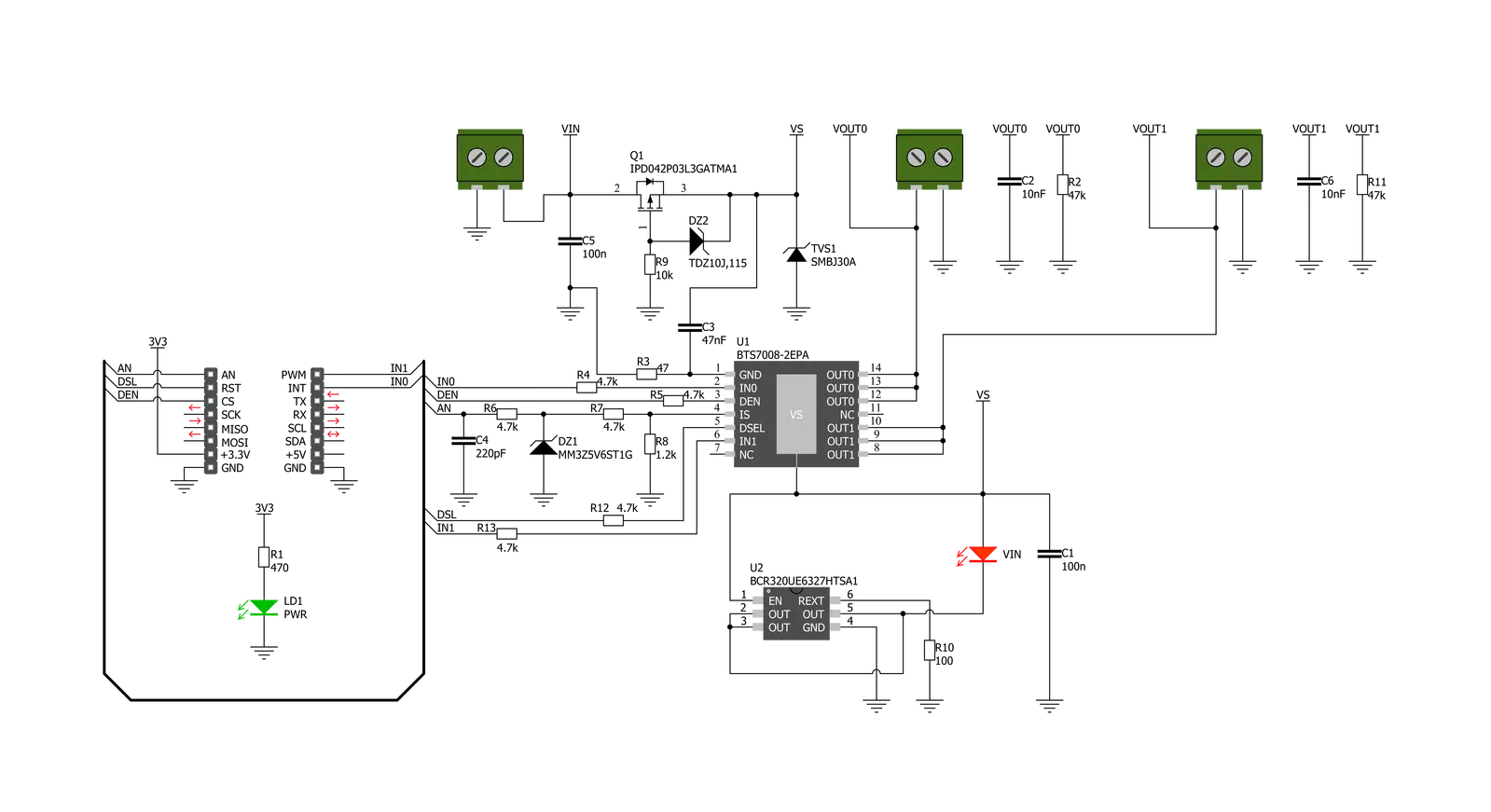
PROFET 2 Click - 7.5A is based on the BTS70082EPAXUMA1, a dual-channel, smart high-side power switch with an Infineon Technologies embedded protection and diagnosis feature. The BTS70082EPAXUMA1 has a driving capability suitable for 7.5A loads and is equipped with "ReverseON" functionality, which causes the power transistor to switch on in reverse polarity. It also offers outstanding energy efficiency with reduced current consumption, state-of-art current sense accuracy, and faster switching/slew rate with no impact on EMC, making it suitable for resistive, inductive, and capacitive loads, replacement of electromechanical relays, fuses, and discrete circuits, and many more. This Click board™ uses five digital pins for direct control. The input pins IN0 and IN1, routed to the PWM and INT pins of the mikroBUS™ socket, activate the
corresponding output channels labeled VOUT0 and VOUT1. Also, the Diagnosis Enable (DEN) pin routed to the CS pin of the mikroBUS™ socket controls the diagnosis and protection circuitry. Combined with IN pins, it enables the selection of appropriate operating states: Sleep, Stand-by, and Active Mode. The BTS70082EPAXUMA1 is protected against overtemperature, overload, reverse power supply(GND and VIN are reverse supplied), and overvoltage. Overtemperature and overload protection work when the device is not in Sleep mode, while overvoltage protection works in all operation modes. For diagnosis purposes, the BTS70082EPAXUMA1 provides a combination of digital and analog signals at the AN pin of the mikroBUS™ socket. Besides, the Diagnosis Selection DSEL pin, routed to the RST pin of the mikroBUS™ socket, selects the channel on which
a diagnosis will be performed. The PROFET 2 Click supports an external power supply for the BTS70082EPAXUMA1, which can be connected to the input terminal labeled as VIN and should be within the range of 4.1V to 28V. VIN has an undervoltage detection circuit, which prevents the activation of the power output stages and diagnosis if the applied voltage is below the undervoltage threshold. A power supply indication, red LED labeled as VIN, indicates the presence of an external power supply. This Click board™ can be operated only with a 3.3V logic voltage level. The board must perform appropriate logic voltage level conversion before using MCUs with different logic levels. Also, it comes equipped with a library containing functions and an example code that can be used as a reference for further development.

Features overview
Development board
Clicker 2 for STM32 is a compact starter development board that brings the flexibility of add-on Click boards™ to your favorite microcontroller, making it a perfect starter kit for implementing your ideas. It comes with an onboard 32-bit ARM Cortex-M4 microcontroller, the STM32F407VGT6 from STMicroelectronics, two mikroBUS™ sockets for Click board™ connectivity, a USB connector, LED indicators, buttons, a JTAG programmer connector, and two 26-pin headers for interfacing with external electronics. Its compact design with clear and easily recognizable silkscreen markings allows you to build gadgets with unique functionalities and features quickly. Each part of the Clicker 2 for
STM32 development kit contains the components necessary for the most efficient operation of the same board. In addition to the possibility of choosing the Clicker 2 for STM32 programming method, using a USB HID mikroBootloader, an external mikroProg connector for STM32 programmer, or through an external ST-LINK V2 programmer, the Clicker 2 board also includes a clean and regulated power supply module for the development kit. It provides two ways of board-powering; through the USB Mini-B cable, where onboard voltage regulators provide the appropriate voltage levels to each component on the board or using a Li-Polymer battery via an onboard battery
connector. All communication methods that mikroBUS™ itself supports are on this board, including the well-established mikroBUS™ socket, reset button, and several user-configurable buttons and LED indicators. Clicker 2 for STM32 is an integral part of the Mikroe ecosystem, allowing you to create a new application in minutes. Natively supported by Mikroe software tools, it covers many aspects of prototyping thanks to a considerable number of different Click boards™ (over a thousand boards), the number of which is growing every day.

Microcontroller Overview
MCU Card / MCU

Architecture
ARM Cortex-M4
MCU Memory (KB)
10
Silicon Vendor
STMicroelectronics
Pin count
100
RAM (Bytes)
100
Used MCU Pins
mikroBUS™ mapper
Take a closer look
Click board™ Schematic
Step by step
Project assembly

Start by selecting your development board and Click board™. Begin with the Clicker 2 for STM32 as your development board.


Software Support
Library Description
This library contains API for PROFET 2 Click driver.
Key functions:
profet2_set_mode- Set mode device mode for specific channel channelprofet2_read_an_pin_voltage- Read AN pin voltage level functionprofet2_set_den- Set diagnostic enable pin state
Open Source
Code example
The complete application code and a ready-to-use project are available through the NECTO Studio Package Manager for direct installation in the NECTO Studio. The application code can also be found on the MIKROE GitHub account.
/*!
 * @file main.c
 * @brief PROFET 2 7A Click Example.
 *
 * # Description
 * This example showcases the ability of the PROFET 2 7A Click board.
 * It configures Host MCU for communication and then enables
 * and disables output channel. Besides that, it reads the voltage
 * of IS pin and calculates current on output for the channel 0.
 *
 * The demo application is composed of two sections :
 *
 * ## Application Init
 * Initialization of the communication modules(ADC and UART)
 * and additional pins for controlling the device.
 *
 * ## Application Task
 * On every iteration of the task device switches between
 * DIAGNOSTIC and OFF mode while it reads the voltage of IS pin
 * and with that calculates current on output for channel 0.
 *
 * @note
 * Formula for calculating current on load:
 * I_load = voltage(IS) x kILIS(5450) / rsens(1.2 kΩ)
 *
 * Click board won't work properly on the PIC18F97J94 MCU card.
 *
 * @author Luka Filipovic
 *
 */

#include "board.h"
#include "log.h"
#include "profet27a.h"

static profet27a_t profet27a;   /**< PROFET 2 7A Click driver object. */
static log_t logger;    /**< Logger object. */

void application_init ( void )
{
    log_cfg_t log_cfg;  /**< Logger config object. */
    profet27a_cfg_t profet27a_cfg;  /**< Click config object. */

    /**
     * Logger initialization.
     * Default baud rate: 115200
     * Default log level: LOG_LEVEL_DEBUG
     * @note If USB_UART_RX and USB_UART_TX
     * are defined as HAL_PIN_NC, you will
     * need to define them manually for log to work.
     * See @b LOG_MAP_USB_UART macro definition for detailed explanation.
     */
    LOG_MAP_USB_UART( log_cfg );
    log_init( &logger, &log_cfg );
    log_info( &logger, " Application Init " );

    // Click initialization.
    profet27a_cfg_setup( &profet27a_cfg );
    PROFET27A_MAP_MIKROBUS( profet27a_cfg, MIKROBUS_1 );
    if ( ADC_ERROR == profet27a_init( &profet27a, &profet27a_cfg ) )
    {
        log_error( &logger, " Application Init Error. " );
        log_info( &logger, " Please, run program again... " );

        for ( ; ; );
    }
    profet27a_default_cfg ( &profet27a );
    log_info( &logger, " Application Task " );
    Delay_ms ( 1000 );
}

void application_task ( void )
{
    static uint8_t mode = PROFET27A_DIAGNOSTIC_ON;
    float profet27a_an_voltage = 0;

    err_t error_val = profet27a_set_mode( &profet27a, PROFET27A_CHANNEL_0, mode );

    if ( error_val )
    {
        log_error( &logger, "Channe/Mode" );
    }

    if ( PROFET27A_DIAGNOSTIC_ON == profet27a.mode )
    {
        mode = PROFET27A_MODE_OFF;
        log_printf( &logger, " > Output ON Channel %u in diagnostic mode\r\n", ( uint16_t )profet27a.channel );
        Delay_ms ( 1000 );
    }
    else
    {
        mode = PROFET27A_DIAGNOSTIC_ON;
        log_printf( &logger, " > Output OFF\r\n" );
    }

    if ( profet27a_read_an_pin_voltage ( &profet27a, &profet27a_an_voltage ) != ADC_ERROR )
    {
        log_printf( &logger, " > IS Voltage \t~ %.3f[V]\r\n", profet27a_an_voltage );

        float current = profet27a_an_voltage * profet27a.kilis / profet27a.rsens;
        log_printf( &logger, " > OUT Current \t~ %.3f[A]\r\n", current );
    }

    log_printf( &logger, "*******************************************\r\n" );

    Delay_ms ( 1000 );
    Delay_ms ( 1000 );
}

int main ( void )
{
    /* Do not remove this line or clock might not be set correctly. */
    #ifdef PREINIT_SUPPORTED
    preinit();
    #endif

    application_init( );

    for ( ; ; )
    {
        application_task( );
    }

    return 0;
}

// ------------------------------------------------------------------------ END
Additional Support
Resources
Category:Power Switch


