Gain valuable thermal insights with MLX90614 and PIC32MX460F512L
Stay chilled and safeguarded - Zero contact needed!
Published Nov 02, 2023
Click board™
IrThermo Click
Dev. board
Clicker 2 for PIC32MX
Compiler
NECTO Studio
MCU
PIC32MX460F512L
Experience a secure temperature monitoring solution that keeps you cool and safe, eliminating the necessity for physical contact
A
A
Hardware Overview
How does it work?
IrThermo Click is based on the MLX90614, a single and dual-zone infrared thermometer from Melexis. This sensor is an IR sensor of a thermopile character. A thermopile sensor is a serially connected thermocouple array with hot junctions on the heat-absorbing membrane. The cold junctions are located on a cold base, providing the reference point for generating the voltage. Due to the low-temperature capacity of the membrane, it will react to the heat radiation, generating voltage via the thermoelectric effect. The ASSP circuitry of the MLX90614 sensor processes the voltage, allowing an accuracy of ±0.5˚C. The MLX90614 sensor is
factory calibrated in a wide temperature range: -40°C to 125°C for sensor temperature and -70°C to 380°C for object temperature. The ASSP circuitry also provides advanced interfacing options for the MCU, with the CRC error checking. The MLX90614 is equipped with a portion of EEPROM, which stores various config parameters, calibration data, and the chip ID address. Changing the values in the EEPROM will only take effect once the device is restarted. IrThermo Click 5V can use the SMBus to communicate with the host MCU using I2C lines of the mikroBUS™ socket. In addition, you can use the 10-bit PWM for data output to the host MCU.
The selection can be made over the SELECT MODE jumper, where the I2C is selected by default. For this Click board™ to work properly, both jumpers should be set to appropriate positions. This Click board™ can be operated only with a 5V logic voltage level. The board must perform appropriate logic voltage level conversion before using MCUs with different logic levels. Also, it comes equipped with a library containing functions and an example code that can be used as a reference for further development.

Features overview
Development board
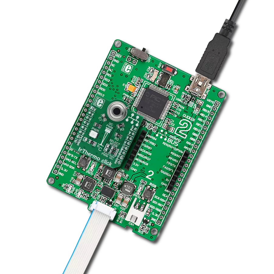
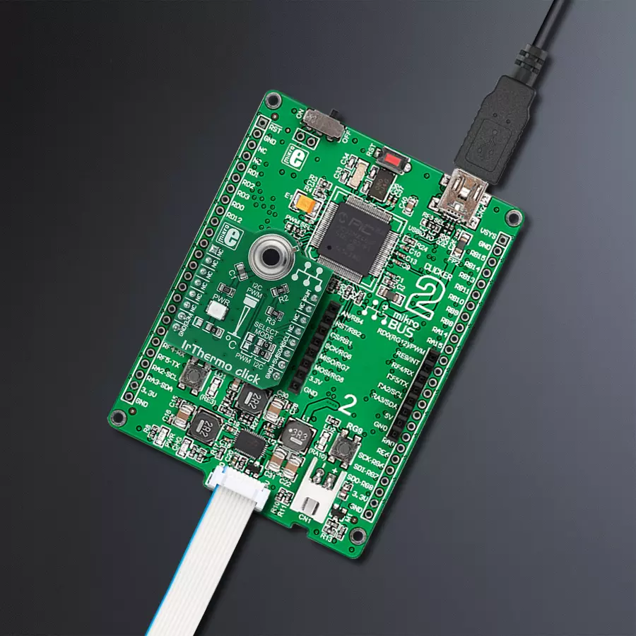
Clicker 2 for PIC32MX is a compact starter development board that brings the flexibility of add-on Click boards™ to your favorite microcontroller, making it a perfect starter kit for implementing your ideas. It comes with an onboard 32-bit MIPS M4K core PIC32 microcontroller, the PIC32MX460F512L from Microchip, two mikroBUS™ sockets for Click board™ connectivity, a USB connector, LED indicators, buttons, a mikroProg programmer connector, and two 26-pin headers for interfacing with external electronics. Its compact design with clear and easily recognizable silkscreen markings allows you to build gadgets with unique functionalities and features quickly. Each part of
the Clicker 2 for PIC32MX development kit contains the components necessary for the most efficient operation of the same board. In addition to the possibility of choosing the Clicker 2 for PIC32MX programming method, using a USB HID mikroBootloader, an external mikroProg connector for PIC32MX programmer, or through an external ICD2/3 programmer, the Clicker 2 board also includes a clean and regulated power supply module for the development kit. It provides two ways of board-powering; through the USB Mini-B cable, where onboard voltage regulators provide the appropriate voltage levels to each component on the board or using a Li-Polymer battery via an
onboard battery connector. All communication methods that mikroBUS™ itself supports are on this board, including the well-established mikroBUS™ socket, reset button, and several user-configurable buttons and LED indicators. Clicker 2 for PIC32MX is an integral part of the Mikroe ecosystem, allowing you to create a new application in minutes. Natively supported by Mikroe software tools, it covers many aspects of prototyping thanks to a considerable number of different Click boards™ (over a thousand boards), the number of which is growing every day.

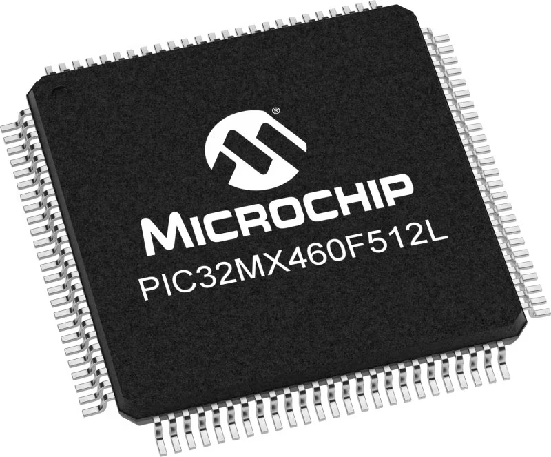
Microcontroller Overview
MCU Card / MCU
Architecture
PIC32
MCU Memory (KB)
512
Silicon Vendor
Microchip
Pin count
100
RAM (Bytes)
32768
Used MCU Pins
mikroBUS™ mapper
Take a closer look
Click board™ Schematic

Step by step
Project assembly

Start by selecting your development board and Click board™. Begin with the Clicker 2 for PIC32MX as your development board.


Track your results in real time
Application Output
1. Application Output - In Debug mode, the 'Application Output' window enables real-time data monitoring, offering direct insight into execution results. Ensure proper data display by configuring the environment correctly using the provided tutorial.

2. UART Terminal - Use the UART Terminal to monitor data transmission via a USB to UART converter, allowing direct communication between the Click board™ and your development system. Configure the baud rate and other serial settings according to your project's requirements to ensure proper functionality. For step-by-step setup instructions, refer to the provided tutorial.

3. Plot Output - The Plot feature offers a powerful way to visualize real-time sensor data, enabling trend analysis, debugging, and comparison of multiple data points. To set it up correctly, follow the provided tutorial, which includes a step-by-step example of using the Plot feature to display Click board™ readings. To use the Plot feature in your code, use the function: plot(*insert_graph_name*, variable_name);. This is a general format, and it is up to the user to replace 'insert_graph_name' with the actual graph name and 'variable_name' with the parameter to be displayed.

Software Support
Library Description
This library contains API for IrThermo Click driver.
Key functions:
irthermo5v_get_t_ambient- Reads Temperature ambient from sensor.irthermo5v_get_t_object- Reads Temperature object from sensor.
Open Source
Code example
The complete application code and a ready-to-use project are available through the NECTO Studio Package Manager for direct installation in the NECTO Studio. The application code can also be found on the MIKROE GitHub account.
/*!
 * @file main.c
 * @brief IrThermo5V Click example
 *
 * # Description
 * This application collects data from the sensor, and logs the results.
 *
 * The demo application is composed of two sections :
 *
 * ## Application Init
 * Initializes IrThermo 5V Driver.
 *
 * ## Application Task
 * Reading Ambient and Object Temperature and displaying the value periodically.
 *
 * @author Stefan Ilic
 *
 */

#include "board.h"
#include "log.h"
#include "irthermo5v.h"

static irthermo5v_t irthermo5v;
static log_t logger;

static float measured_temperature;
static float object_temperature;

void application_init ( void ) {
    log_cfg_t log_cfg;  /**< Logger config object. */
    irthermo5v_cfg_t irthermo5v_cfg;  /**< Click config object. */

    /**
     * Logger initialization.
     * Default baud rate: 115200
     * Default log level: LOG_LEVEL_DEBUG
     * @note If USB_UART_RX and USB_UART_TX
     * are defined as HAL_PIN_NC, you will
     * need to define them manually for log to work.
     * See @b LOG_MAP_USB_UART macro definition for detailed explanation.
     */
    LOG_MAP_USB_UART( log_cfg );
    log_init( &logger, &log_cfg );
    log_info( &logger, " Application Init \r\n " );
    log_printf( &logger, "------------------------------\r\n " );

    // Click initialization.
    irthermo5v_cfg_setup( &irthermo5v_cfg );
    IRTHERMO5V_MAP_MIKROBUS( irthermo5v_cfg, MIKROBUS_1 );
    err_t init_flag = irthermo5v_init( &irthermo5v, &irthermo5v_cfg );
    if ( I2C_MASTER_ERROR == init_flag ) {
        log_error( &logger, " Application Init Error. " );
        log_info( &logger, " Please, run program again... " );

        for ( ; ; );
    }

    log_info( &logger, " Application Task \r\n" );
    log_printf( &logger, "------------------------------\r\n " );
}

void application_task ( void ) {
    measured_temperature = irthermo5v_get_t_ambient( &irthermo5v );
    object_temperature = irthermo5v_get_t_object( &irthermo5v );
    log_printf( &logger, " Ambient Temperature: %.2f C\r\n ", measured_temperature );
    log_printf( &logger, " Object  Temperature: %.2f C\r\n ", object_temperature );
    log_printf( &logger, "------------------------------\r\n " );
    Delay_ms ( 1000 );
}

int main ( void )
{
    /* Do not remove this line or clock might not be set correctly. */
    #ifdef PREINIT_SUPPORTED
    preinit();
    #endif

    application_init( );

    for ( ; ; )
    {
        application_task( );
    }

    return 0;
}

// ------------------------------------------------------------------------ END
Additional Support
Resources
Category:Temperature & humidity