Modernize user experience with IQS263B and MK64FN1M0VDC12
Upgrade touch experience

Published Aug 09, 2023
Click board™
Cap Wheel 2 Click
Dev. board
Clicker 2 for Kinetis
Compiler
NECTO Studio
MCU
MK64FN1M0VDC12
This capacitive solution aims to revolutionize user interaction, providing a responsive and intuitive means to control devices with a simple touch
A
A
Hardware Overview
How does it work?
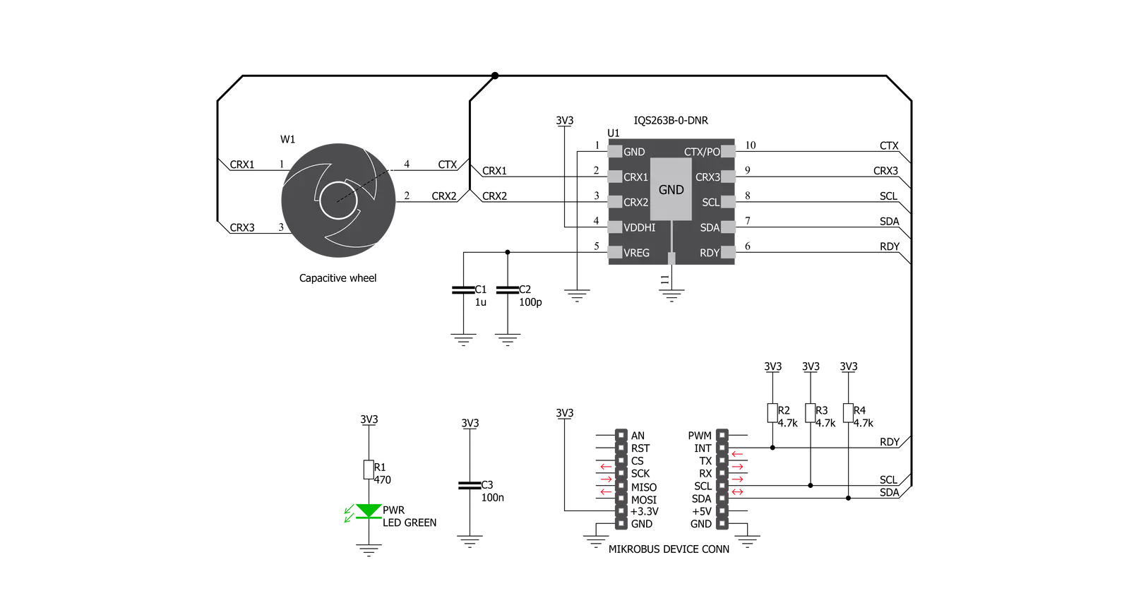
Cap Wheel 2 Click is based on the IQS263B, ProxSense® IC, a 3-channel projected (or self) capacitive proximity and touch controller from Azoteq. This IC has advanced features such as auto drift compensation, up to 80Hz report rate, long proximity range, automatic adjustment for optimal performance (ATI), and a configurable 8-bit 2/3 channel slider or 3-channel scroll wheel. These features enable CAP Wheel 2 click to exhibit reliable and accurate touch detection. Capacitive touch sensing is based on detecting a change in capacitance due to the influence of a foreign
object. The capacitance of the sensor, also known as the antenna, is measured and monitored, and if a significant change occurs after processing by the detection integrator, a touch event is acknowledged. CAP Wheel 2 Click is designed with these requirements in mind, and the electrodes are „Self-Capacitive Wheel“ shaped. The IQS263B IC interfaces to a master controller via a 3-wire (SDA, SCL, and RDY) serial interface bus that is I2C™ compatible, with a maximum communication speed of 400kbit/s. The host MCU can force communication anytime by pulling the
RDY line low. The communication will start directly following the current conversion cycle. If the watchdog timer terminates the event, the device will reset. After every power-on cycle, the device will recalibrate itself. It will take some time, so it should be considered when building custom applications. MikroElektronika provides libraries and the demo application to be used as a reference for future designs. As mentioned before, this Click board™ is I2C compatible and uses SCL, SDA, and RDY pins for communication routed to SCL, SDA, and INT pins on mikroBUS™.


Features overview
Development board
Clicker 2 for Kinetis is a compact starter development board that brings the flexibility of add-on Click boards™ to your favorite microcontroller, making it a perfect starter kit for implementing your ideas. It comes with an onboard 32-bit ARM Cortex-M4F microcontroller, the MK64FN1M0VDC12 from NXP Semiconductors, two mikroBUS™ sockets for Click board™ connectivity, a USB connector, LED indicators, buttons, a JTAG programmer connector, and two 26-pin headers for interfacing with external electronics. Its compact design with clear and easily recognizable silkscreen markings allows you to build gadgets with unique functionalities and
features quickly. Each part of the Clicker 2 for Kinetis development kit contains the components necessary for the most efficient operation of the same board. In addition to the possibility of choosing the Clicker 2 for Kinetis programming method, using a USB HID mikroBootloader or an external mikroProg connector for Kinetis programmer, the Clicker 2 board also includes a clean and regulated power supply module for the development kit. It provides two ways of board-powering; through the USB Micro-B cable, where onboard voltage regulators provide the appropriate voltage levels to each component on the board, or
using a Li-Polymer battery via an onboard battery connector. All communication methods that mikroBUS™ itself supports are on this board, including the well-established mikroBUS™ socket, reset button, and several user-configurable buttons and LED indicators. Clicker 2 for Kinetis is an integral part of the Mikroe ecosystem, allowing you to create a new application in minutes. Natively supported by Mikroe software tools, it covers many aspects of prototyping thanks to a considerable number of different Click boards™ (over a thousand boards), the number of which is growing every day.

Microcontroller Overview
MCU Card / MCU

Architecture
ARM Cortex-M4
MCU Memory (KB)
1024
Silicon Vendor
NXP
Pin count
121
RAM (Bytes)
262144
Used MCU Pins
mikroBUS™ mapper
Take a closer look
Click board™ Schematic
Step by step
Project assembly

Start by selecting your development board and Click board™. Begin with the Clicker 2 for Kinetis as your development board.


Track your results in real time
Application Output
1. Application Output - In Debug mode, the 'Application Output' window enables real-time data monitoring, offering direct insight into execution results. Ensure proper data display by configuring the environment correctly using the provided tutorial.

2. UART Terminal - Use the UART Terminal to monitor data transmission via a USB to UART converter, allowing direct communication between the Click board™ and your development system. Configure the baud rate and other serial settings according to your project's requirements to ensure proper functionality. For step-by-step setup instructions, refer to the provided tutorial.

3. Plot Output - The Plot feature offers a powerful way to visualize real-time sensor data, enabling trend analysis, debugging, and comparison of multiple data points. To set it up correctly, follow the provided tutorial, which includes a step-by-step example of using the Plot feature to display Click board™ readings. To use the Plot feature in your code, use the function: plot(*insert_graph_name*, variable_name);. This is a general format, and it is up to the user to replace 'insert_graph_name' with the actual graph name and 'variable_name' with the parameter to be displayed.

Software Support
Library Description
This library contains API for CAP Wheel 2 Click driver.
Key functions:
capwheel2_int_get- This function gets state of INT pincapwheel2_wait_for_rdy- This function waits for RDY pin to transition from HIGH to LOW state.
Open Source
Code example
The complete application code and a ready-to-use project are available through the NECTO Studio Package Manager for direct installation in the NECTO Studio. The application code can also be found on the MIKROE GitHub account.
/*!
 * \file
 * \brief CapWheel2 Click example
 *
 * # Description
 * This example sets basic device configuration; Contains function for waiting RDY(INT) pin, function for getting RDY(INT) pin state,
 * function for I2C read and write with waiting for RDY(INT) pin and without waiting for RDY(INT) pin.
 *
 * The demo application is composed of two sections :
 *
 * ## Application Init
 * Initializes CAP Wheel 2 device
 *
 * ## Application Task
 * Executes one of three 'capwheel2_get_xxx_task( )' functions
 *
 * Additional Functions :
 *
 * - capwheel2_error( ) - Logs error message and blocks code execution in endless while loop
 * - capwheel2_get_channels_task( ) - Logs active channels in touch and halt bytes ( channels: CH0 - proximity channel, CH1, CH2, CH3 )
 * - capwheel2_get_gesture_task( ) - Logs active gestures ( gestures: tap, touch, proximity )
 * - capwheel2_get_channel_counts_task( ) - Logs channel count values for each channel
 * - capwheel2_get_channels_touch( ) - Logs touch byte active channels ( exectuted by 'capwheel2_get_channels_task( )' function )
 * - capwheel2_get_channels_halt( ) - Logs halt byte active channels ( exectuted by 'capwheel2_get_channels_task( )' function )

 * \author MikroE Team
 *
 */
// ------------------------------------------------------------------- INCLUDES

#include "board.h"
#include "log.h"
#include "capwheel2.h"

// ------------------------------------------------------------------ VARIABLES

static capwheel2_t capwheel2;
static log_t logger;

static uint8_t data_buffer[ 30 ];

static uint16_t channel_0_counts;
static uint16_t channel_1_counts;
static uint16_t channel_2_counts;
static uint16_t channel_3_counts;
// ------------------------------------------------------- ADDITIONAL FUNCTIONS

void capwheel2_error( )
{
    log_info( &logger, "> error : reset system" );
    while( 1 );
}

void capwheel2_get_channels_touch( )
{
    switch ( data_buffer[ 0 ] )
    {
        case 0x00 :
        {
            log_printf( &logger, ">     |     |     |     <   \r\n" );
            break;
        }
        case 0x01 :
        {
            log_printf( &logger, ">     |     |     | CH0 <   \r\n" );
            break;
        }
        case 0x02 :
        {
            log_printf( &logger, ">     |     | CH1 |     <   \r\n" );
            break;
        }
        case 0x03 :
        {
            log_printf( &logger, ">     |     | CH1 | CH0 <   \r\n" );
            break;
        }
        case 0x04 :
        {
            log_printf( &logger, ">     | CH2 |     |     <   \r\n" );
            break;
        }
        case 0x05 :
        {
            log_printf( &logger, ">     | CH2 |     | CH0 <   \r\n" );
            break;
        }
        case 0x06 :
        {
            log_printf( &logger, ">     | CH2 | CH1 |     <   \r\n" );
            break;
        }
        case 0x07 :
        {
            log_printf( &logger, ">     | CH2 | CH1 | CH0 <   \r\n" );
            break;
        }
        case 0x08 :
        {
            log_printf( &logger, "> CH3 |     |     |     <   \r\n" );
            break;
        }
        case 0x09 :
        {
            log_printf( &logger, "> CH3 |     |     | CH0 <   \r\n" );
            break;
        }
        case 0x0A :
        {
            log_printf( &logger, "> CH3 |     | CH1 |     <   \r\n" );
            break;
        }
        case 0x0B :
        {
            log_printf( &logger, "> CH3 |     | CH1 | CH0 <   \r\n" );
            break;
        }
        case 0x0C :
        {
            log_printf( &logger, "> CH3 | CH2 |     |     <   \r\n" );
            break;
        }
        case 0x0D :
        {
            log_printf( &logger, "> CH3 | CH2 |     | CH0 <   \r\n" );
            break;
        }
        case 0x0E :
        {
            log_printf( &logger, "> CH3 | CH2 | CH1 |     <   \r\n" );
            break;
        }
        case 0x0F :
        {
            log_printf( &logger, "> CH3 | CH2 | CH1 | CH0 <   \r\n" );
            break;
        }
        default :
        {
            break;
        }
    }
}

void capwheel2_get_channels_halt( )
{
    switch ( data_buffer[ 1 ] )
    {
        case 0x00 :
        {
            log_printf( &logger, ">     |     |     |     <\r\n" );
            break;
        }
        case 0x01 :
        {
            log_printf( &logger, ">     |     |     | CH0 <\r\n" );
            break;
        }
        case 0x02 :
        {
            log_printf( &logger, ">     |     | CH1 |     <\r\n" );
            break;
        }
        case 0x03 :
        {
            log_printf( &logger, ">     |     | CH1 | CH0 <\r\n" );
            break;
        }
        case 0x04 :
        {
            log_printf( &logger, ">     | CH2 |     |     <\r\n" );
            break;
        }
        case 0x05 :
        {
            log_printf( &logger, ">     | CH2 |     | CH0 <\r\n" );
            break;
        }
        case 0x06 :
        {
            log_printf( &logger, ">     | CH2 | CH1 |     <\r\n" );
            break;
        }
        case 0x07 :
        {
            log_printf( &logger, ">     | CH2 | CH1 | CH0 <\r\n" );
            break;
        }
        case 0x08 :
        {
            log_printf( &logger, "> CH3 |     |     |     <\r\n" );
            break;
        }
        case 0x09 :
        {
            log_printf( &logger, "> CH3 |     |     | CH0 <\r\n" );
            break;
        }
        case 0x0A :
        {
            log_printf( &logger, "> CH3 |     | CH1 |     <\r\n" );
            break;
        }
        case 0x0B :
        {
            log_printf( &logger, "> CH3 |     | CH1 | CH0 <\r\n" );
            break;
        }
        case 0x0C :
        {
            log_printf( &logger, "> CH3 | CH2 |     |     <\r\n" );
            break;
        }
        case 0x0D :
        {
            log_printf( &logger, "> CH3 | CH2 |     | CH0 <\r\n" );
            break;
        }
        case 0x0E :
        {
            log_printf( &logger, "> CH3 | CH2 | CH1 |     <\r\n" );
            break;
        }
        case 0x0F :
        {
            log_printf( &logger, "> CH3 | CH2 | CH1 | CH0 <\r\n" );
            break;
        }
        default :
        {
            break;
        }
    }
}

void capwheel2_get_channels_task( )
{
    if ( capwheel2_i2c_read_wait( &capwheel2, CAPWHEEL2_TOUCH_BYTES, &data_buffer[ 0 ], 2 ) )
    {
        capwheel2_error( );
    }
    log_printf( &logger, " ");
    log_printf( &logger, ">      TOUCH BYTES      <\r\n" );
    log_printf( &logger, ">      HALT  BYTES      <\r\n" );
    capwheel2_get_channels_touch( );
    capwheel2_get_channels_halt( );
    Delay_ms ( 150 );
}

void capwheel2_get_gesture_task( )
{
    if ( capwheel2_i2c_read_wait( &capwheel2, CAPWHEEL2_SYS_FLAGS, &data_buffer[ 0 ], 2 ) )
    {
        capwheel2_error( );
    }

    if ( ( data_buffer[ 1 ] & CAPWHEEL2_TAP_MASK ) == CAPWHEEL2_TAP_MASK)
    {
        log_printf( &logger, "> TAP\r\n" );
    }
    else if ( ( data_buffer[ 1 ] & CAPWHEEL2_TOUCH_MASK ) == CAPWHEEL2_TOUCH_MASK)
    {
        log_printf( &logger, "> TOUCH\r\n" );
    }
    else if ( ( data_buffer[ 1 ] & CAPWHEEL2_PROX_MASK ) == CAPWHEEL2_PROX_MASK)
    {
        log_printf( &logger, "> PROX\r\n" );
    }
    Delay_ms ( 800 );
}

void capwheel2_get_channel_counts_task( )
{
    if (capwheel2_i2c_read_wait( &capwheel2, CAPWHEEL2_COUNTS, &data_buffer[ 0 ], 10))
    {
        capwheel2_error( );
    }
    channel_0_counts = data_buffer[ 3 ];
    channel_0_counts <<= 8;
    channel_0_counts |= data_buffer[ 2 ];
    channel_1_counts = data_buffer[ 5 ];
    channel_1_counts <<= 8;
    channel_1_counts |= data_buffer[ 4 ];
    channel_2_counts = data_buffer[ 7 ];
    channel_2_counts <<= 8;
    channel_2_counts |= data_buffer[ 6 ];
    channel_3_counts = data_buffer[ 9 ];
    channel_3_counts <<= 8;
    channel_3_counts |= data_buffer[ 8 ];

    log_printf( &logger, "> Channel 0  counts : %u \r\n", channel_0_counts );
    log_printf( &logger, "> Channel 1  counts : %u \r\n", channel_1_counts );
    log_printf( &logger, "> Channel 2  counts : %u \r\n", channel_2_counts );

    log_info( &logger, " ");
    Delay_ms ( 150 );
}


// ------------------------------------------------------ APPLICATION FUNCTIONS

void application_init ( void )
{
    log_cfg_t log_cfg;
    capwheel2_cfg_t cfg;

    /**
     * Logger initialization.
     * Default baud rate: 115200
     * Default log level: LOG_LEVEL_DEBUG
     * @note If USB_UART_RX and USB_UART_TX
     * are defined as HAL_PIN_NC, you will
     * need to define them manually for log to work.
     * See @b LOG_MAP_USB_UART macro definition for detailed explanation.
     */
    LOG_MAP_USB_UART( log_cfg );
    log_init( &logger, &log_cfg );
    log_info( &logger, "---- Application Init ----" );

    //  Click initialization.

    capwheel2_cfg_setup( &cfg );
    CAPWHEEL2_MAP_MIKROBUS( cfg, MIKROBUS_1 );
    capwheel2_init( &capwheel2, &cfg );
}

void application_task ( void )
{
    capwheel2_get_channels_task( );
}

int main ( void )
{
    /* Do not remove this line or clock might not be set correctly. */
    #ifdef PREINIT_SUPPORTED
    preinit();
    #endif

    application_init( );

    for ( ; ; )
    {
        application_task( );
    }

    return 0;
}


// ------------------------------------------------------------------------ END


