Achieve touch-activated control with IQS211B and PIC32MZ2048EFM100
Single-channel capacitive controller for highly sensitive touch detection capabilities

Published Oct 15, 2024
Click board™
Cap Touch 4 Click
Dev. board
Curiosity PIC32 MZ EF
Compiler
NECTO Studio
MCU
PIC32MZ2048EFM100
Add touch-based controls into various human-interface scenarios
A
A
Hardware Overview
How does it work?
Cap Touch 4 Click is based on the IQS211B, a single-channel capacitive proximity and touch controller from Azoteq, designed for applications requiring activation or wake-on-touch functionality. The IQS211B uses ProxSense® technology to provide highly sensitive self-capacitance measurements, making it ideal for proximity-activated solutions, human interface devices, and white goods. The onboard touch-sensing pad is marked on the front side of the board, offering a defined circular touch-sensing area, ensuring easy user interaction. Additionally, it includes signal conditioning to compensate for parasitic capacitance and provide accurate signal gain, ensuring reliable touch and proximity detection in varying environmental conditions. As mentioned, the IQS211B offers advanced features such as automatic detection and environmental compensation through its integrated finite state machine, eliminating the need for constant host MCU interaction. This allows for smooth operation
without external interference. It also includes an integrated LDO regulator to enhance immunity against power supply noise, an internal oscillator for consistent performance, and built-in calibration capacitors to maintain accuracy over time. This Click board™ is designed in a unique format supporting the newly introduced MIKROE feature called "Click Snap." Unlike the standardized version of Click boards, this feature allows the main sensor area to become movable by breaking the PCB, opening up many new possibilities for implementation. Thanks to the Snap feature, the IQS211B can operate autonomously by accessing its signals directly on the pins marked 1-8. Additionally, the Snap part includes a specified and fixed screw hole position, enabling users to secure the Snap board in their desired location. Cap Touch 4 Click uses a standard 2-wire I2C interface to communicate with the host MCU. During standard operation, the IQS211B sensor performs capacitance conversions and conserves energy by
entering a low-power Sleep mode. The duration of this sleep period is adjustable and controlled by the sample period settings. A key feature of the IQS211B is its ability to activate its wake-up function, enabling it to respond to any activity detected on the I2C bus immediately. Once awakened, the sensor begins conversions without delay, ensuring prompt responsiveness in real-time applications. The device uses a fixed I2C address of 0x47 for ease of integration, simplifying communication setup across various systems. This Click board™ can be operated only with a 3.3V logic voltage level and activated via the EN pin of the mikroBUS™ socket, providing a power-enabling function. The board must perform appropriate logic voltage level conversion before using MCUs with different logic levels. Also, it comes equipped with a library containing functions and an example code that can be used as a reference for further development.

Features overview
Development board
Curiosity PIC32 MZ EF development board is a fully integrated 32-bit development platform featuring the high-performance PIC32MZ EF Series (PIC32MZ2048EFM) that has a 2MB Flash, 512KB RAM, integrated FPU, Crypto accelerator, and excellent connectivity options. It includes an integrated programmer and debugger, requiring no additional hardware. Users can expand
functionality through MIKROE mikroBUS™ Click™ adapter boards, add Ethernet connectivity with the Microchip PHY daughter board, add WiFi connectivity capability using the Microchip expansions boards, and add audio input and output capability with Microchip audio daughter boards. These boards are fully integrated into PIC32’s powerful software framework, MPLAB Harmony,
which provides a flexible and modular interface to application development a rich set of inter-operable software stacks (TCP-IP, USB), and easy-to-use features. The Curiosity PIC32 MZ EF development board offers expansion capabilities making it an excellent choice for a rapid prototyping board in Connectivity, IOT, and general-purpose applications.

Microcontroller Overview
MCU Card / MCU

Architecture
PIC32
MCU Memory (KB)
2048
Silicon Vendor
Microchip
Pin count
100
RAM (Bytes)
524288
Used MCU Pins
mikroBUS™ mapper
Take a closer look
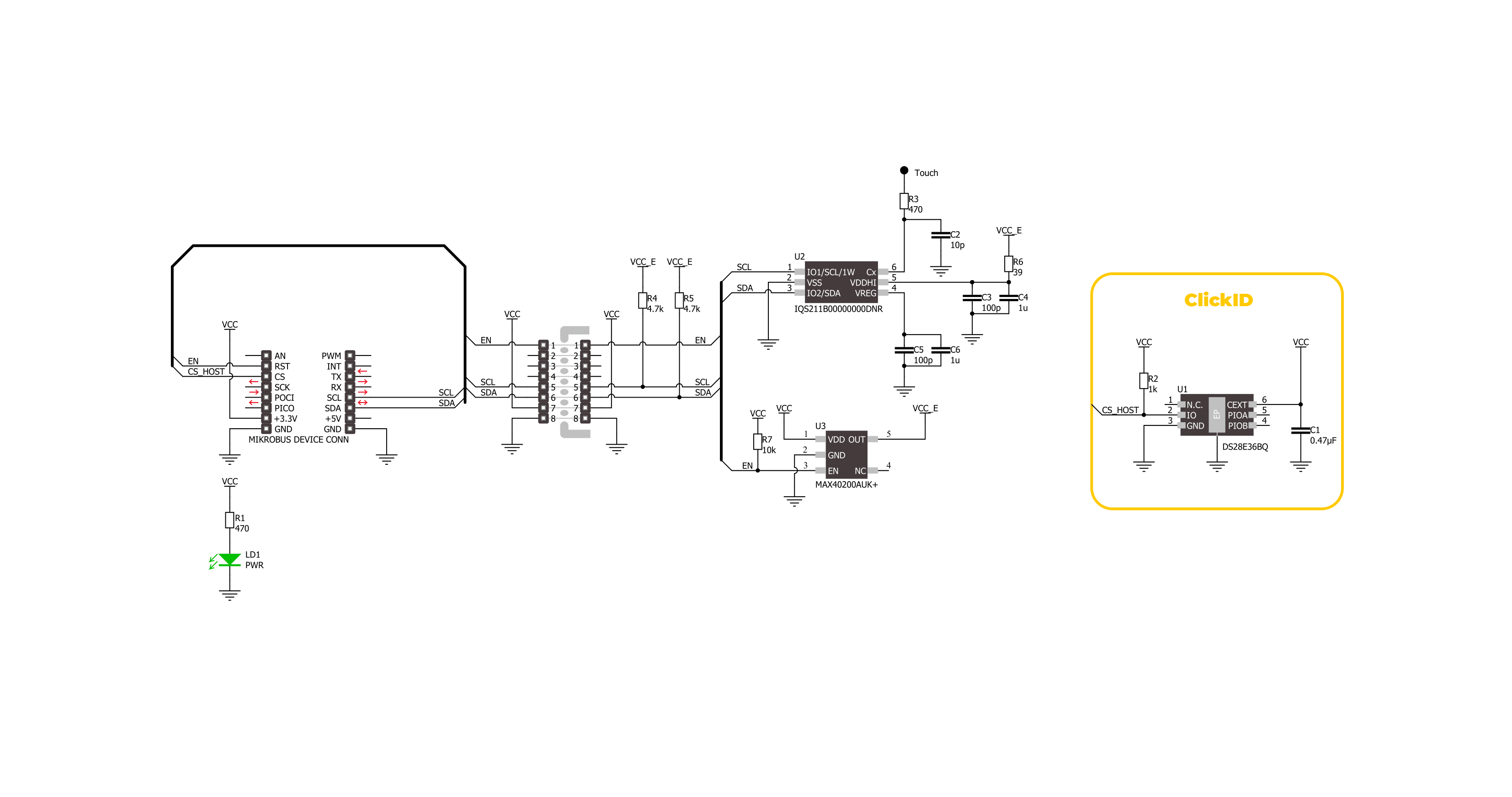
Click board™ Schematic
Step by step
Project assembly

Start by selecting your development board and Click board™. Begin with the Curiosity PIC32 MZ EF as your development board.


Track your results in real time
Application Output
1. Application Output - In Debug mode, the 'Application Output' window enables real-time data monitoring, offering direct insight into execution results. Ensure proper data display by configuring the environment correctly using the provided tutorial.

2. UART Terminal - Use the UART Terminal to monitor data transmission via a USB to UART converter, allowing direct communication between the Click board™ and your development system. Configure the baud rate and other serial settings according to your project's requirements to ensure proper functionality. For step-by-step setup instructions, refer to the provided tutorial.

3. Plot Output - The Plot feature offers a powerful way to visualize real-time sensor data, enabling trend analysis, debugging, and comparison of multiple data points. To set it up correctly, follow the provided tutorial, which includes a step-by-step example of using the Plot feature to display Click board™ readings. To use the Plot feature in your code, use the function: plot(*insert_graph_name*, variable_name);. This is a general format, and it is up to the user to replace 'insert_graph_name' with the actual graph name and 'variable_name' with the parameter to be displayed.

Software Support
Library Description
This library contains API for Cap Touch 4 Click driver.
Key functions:
captouch4_read_system_flags- This function reads the system flags register.captouch4_read_cap_counts- This function reads the counts number directly proportional to capacitance. The system is calibrated to make the counts as sensitive as possible to changes in capacitance for relative measurements.captouch4_read_lta- This function reads the long-term averate (LTA) value. The LTA is used as reference to compare with capacitance counts.
Open Source
Code example
The complete application code and a ready-to-use project are available through the NECTO Studio Package Manager for direct installation in the NECTO Studio. The application code can also be found on the MIKROE GitHub account.
/*!
* @file main.c
* @brief Cap Touch 4 Click example
*
* # Description
* This example demonstrates the use of Cap Touch 4 Click board by reading
* the proximity, touch, and movement events.
*
* The demo application is composed of two sections :
*
* ## Application Init
* Initializes the driver and performs the Click default configuration.
*
* ## Application Task
* Reads the proximity, touch, and movement events and approximately displays
* the results on the USB UART every 200ms. The capacitance counts and the long-term
* average values are also displayed.
*
* @author Stefan Filipovic
*
*/
#include "board.h"
#include "log.h"
#include "captouch4.h"
static captouch4_t captouch4;
static log_t logger;
void application_init ( void )
{
log_cfg_t log_cfg; /**< Logger config object. */
captouch4_cfg_t captouch4_cfg; /**< Click config object. */
/**
* Logger initialization.
* Default baud rate: 115200
* Default log level: LOG_LEVEL_DEBUG
* @note If USB_UART_RX and USB_UART_TX
* are defined as HAL_PIN_NC, you will
* need to define them manually for log to work.
* See @b LOG_MAP_USB_UART macro definition for detailed explanation.
*/
LOG_MAP_USB_UART( log_cfg );
log_init( &logger, &log_cfg );
log_info( &logger, " Application Init " );
// Click initialization.
captouch4_cfg_setup( &captouch4_cfg );
CAPTOUCH4_MAP_MIKROBUS( captouch4_cfg, MIKROBUS_1 );
if ( I2C_MASTER_ERROR == captouch4_init( &captouch4, &captouch4_cfg ) )
{
log_error( &logger, " Communication init." );
for ( ; ; );
}
if ( CAPTOUCH4_ERROR == captouch4_default_cfg ( &captouch4 ) )
{
log_error( &logger, " Default configuration." );
for ( ; ; );
}
log_info( &logger, " Application Task " );
}
void application_task ( void )
{
uint8_t sys_flags = 0;
uint8_t movement = 0;
uint16_t cap_counts = 0;
uint16_t lta = 0;
if ( CAPTOUCH4_OK == captouch4_read_system_flags ( &captouch4, &sys_flags ) )
{
if ( sys_flags & CAPTOUCH4_SYSFLAGS0_PROX )
{
log_printf( &logger, " Proximity detected\r\n" );
}
if ( sys_flags & CAPTOUCH4_SYSFLAGS0_TOUCH )
{
log_printf( &logger, " Touch detected\r\n" );
}
if ( sys_flags & CAPTOUCH4_SYSFLAGS0_MOVEMENT )
{
if ( CAPTOUCH4_OK == captouch4_read_movement ( &captouch4, &movement ) )
{
log_printf( &logger, " Movement detected: %u\r\n", ( uint16_t ) movement );
}
}
if ( ( sys_flags & CAPTOUCH4_SYSFLAGS0_MOVEMENT ) ||
( sys_flags & CAPTOUCH4_SYSFLAGS0_PROX ) ||
( sys_flags & CAPTOUCH4_SYSFLAGS0_TOUCH ) )
{
if ( CAPTOUCH4_OK == captouch4_read_cap_counts ( &captouch4, &cap_counts ) )
{
log_printf( &logger, " Capacitance counts: %u\r\n", cap_counts );
}
if ( CAPTOUCH4_OK == captouch4_read_lta ( &captouch4, <a ) )
{
log_printf( &logger, " Long-term average: %u\r\n\n", lta );
}
}
else
{
log_printf( &logger, " No detected events\r\n\n" );
}
}
Delay_ms ( 200 );
}
int main ( void )
{
/* Do not remove this line or clock might not be set correctly. */
#ifdef PREINIT_SUPPORTED
preinit();
#endif
application_init( );
for ( ; ; )
{
application_task( );
}
return 0;
}
// ------------------------------------------------------------------------ END


