Master electrical power analysis with MCP3910 and PIC18F67K40
Voltage, current, and beyond

Published Sep 29, 2023
Click board™
PWR Meter 2 click
Dev. board
Clicker 2 for PIC18FK
Compiler
NECTO Studio
MCU
PIC18F67K40
Our groundbreaking power monitoring solution is designed to provide unrivaled accuracy in measuring and monitoring voltage and current values, ensuring optimal performance and efficiency in your electrical systems.
A
A
Hardware Overview
How does it work?
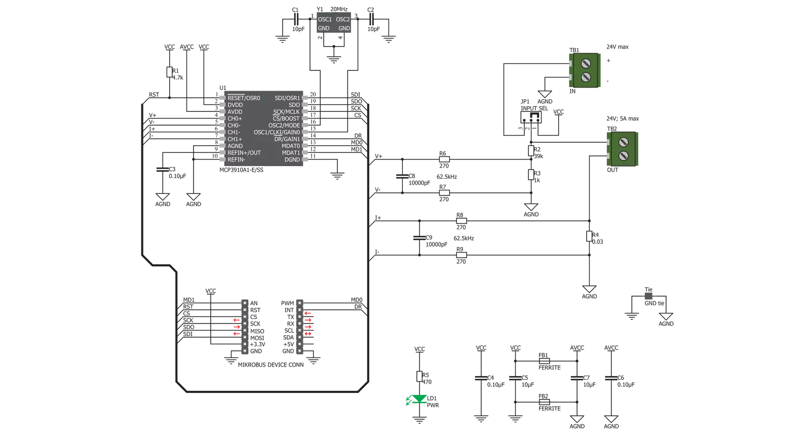
PWR Meter 2 Click is based on the MCP3910, an integrated two-channel analog front-end (AFE) device from Microchip. This IC is composed of several sections, aimed at accurate capturing of the input voltage. Two sigma-delta input A/D converters used with the internal reference voltage of 1.2V with very low thermal drift, reducing the measurement noise at a minimum, yielding Signal to Noise ratio (SNR) up to 96dB. The input ADCs are fully configurable and can be set to work in 16-bit or 24-bit mode, can use oversampling ratio from 32 X up to 4096 X, gain ratio from 1 X to 32 X, and 24-bit digital offset and gain error correction for each ADC channel. The Click board™ is clocked by a 20MHz crystal. However, it is up to the user to set the pre-scalers correctly, according to the datasheet of the MCP3910. However, the included library offers functions which take care about correct settings. High clock speed allows maximum oversampling rate (OSR) to be used, allowing the best performance to be achieved, but consuming more power at the same time. The voltage and current readings are performed over two differential ADC input channels of the MCP3910 itself. The CH0 (Channel 0) is connected to a resistor voltage
divider, allowing it to measure up to 0.6V when the input voltage is 24V, which is the maximum voltage at the input terminal. Although the voltage across a differential input on the ADC channel can go up to ±2V, it is recommended by the manufacturer to stay within the ±0.6V margin to achieve optimal harmonic distortion and noise ratios, which might affect the measurement accuracy. The CH1 (Channel 1) differential input is connected to the shunt resistor of 0.03 Ω. A small voltage drop is measured by the ADC, allowing up to 5A of current to be measured. More of 5A might destroy the shunt resistor so it is not recommended going over 5A. The current measurement is done by connecting the load in series with the Click board™, so the shunt value of 0.03Ω will not introduce significant error or influence the current through the load. The measurement is performed using so-called Kelvin connections, where the main trace carries the majority of the current, while thin traces are used to measure the voltage across the shunt, reducing the current running through the ADC section of the IC itself. Additional 270 Ω resistors reduce the current through the ADC even further. The MCP3910 contains several additional pins, which
are used to simplify the implementation and reduce the bulkiness of the firmware application. The Data Ready pin can be used to trigger an interrupt event on the host MCU when there is conversion data ready to be read. This simplifies the MCU performance greatly, saving it from having to poll status bits in order to determine if the data is ready for reading. The Data Ready pin is routed to the mikroBUS™ INT pin, labeled as the DR. Two Modulator Output pins are also routed to the mikroBUS™. These pins offer direct 1-bit data output directly from the delta-sigma modulators for a user-defined MCU or DSP filtering, overriding the internal SINC filter, which is turned off if these pins are activated. The DR pin is also disabled when these pins are enabled. MDAT0 and MDAT1 pins offer modulator output from ADC channel 0 and ADC channel 1. These pins are routed to mikroBUS™ pins PWM and AN and are labeled as MDT0 and MDT1, respectively. As already mentioned, the Click board™ offers measurement of either internal power supply from the mikroBUS™, or the externally with up to 24V and 5A. To select the measurement target, the SMD jumper labeled INPUT SEL should be switched to the desired position.

Features overview
Development board
Clicker 2 for PIC18FK is a compact starter development board that brings the flexibility of add-on Click boards™ to your favorite microcontroller, making it a perfect starter kit for implementing your ideas. It comes with an onboard 8-bit PIC microcontroller, the PIC18F67K40 from Microchip, two mikroBUS™ sockets for Click board™ connectivity, a USB connector, LED indicators, buttons, a mikroProg connector, and two 26-pin headers for interfacing with external electronics. Its compact design with clear and easily recognizable silkscreen markings allows you to build gadgets with unique functionalities and features quickly.
Each part of the Clicker 2 for PIC18FK development kit contains the components necessary for the most efficient operation of the same board. In addition to the possibility of choosing the Clicker 2 for PIC18FK programming method: using UART mikroBootloader, an external mikroProg connector for PIC18FK programmer, or through Xpress bootloader, the Clicker 2 board also includes a clean and regulated power supply module for the development kit. It provides two ways of board-powering; through the USB Micro-B cable, where onboard voltage regulators provide the appropriate voltage levels to each component
on the board, or using a Li-Polymer battery via an onboard battery connector. All communication methods that mikroBUS™ itself supports are on this board, including the well-established mikroBUS™ socket, reset button, and several user-configurable buttons and LED indicators. Clicker 2 for PIC18FK is an integral part of the Mikroe ecosystem, allowing you to create a new application in minutes. Natively supported by Mikroe software tools, it covers many aspects of prototyping thanks to a considerable number of different Click boards™ (over a thousand boards), the number of which is growing every day.

Microcontroller Overview
MCU Card / MCU
Architecture
PIC
MCU Memory (KB)
128
Silicon Vendor
Microchip
Pin count
64
RAM (Bytes)
3562
Used MCU Pins
mikroBUS™ mapper
Take a closer look
Click board™ Schematic
Step by step
Project assembly

Start by selecting your development board and Click board™. Begin with the Clicker 2 for PIC18FK as your development board.


Software Support
Library Description
This library contains API for PWR Meter 2 Click driver.
Key functions:
pwrmeter2_get_data- This function gets the calculated voltage( V ), current( A ) and power( W ) datapwrmeter2_write_reg- This function writes 24-bit data to the registerpwrmeter2_read_reg- This function reads the desired number of 24-bit data from the register/registers.
Open Source
Code example
The complete application code and a ready-to-use project are available through the NECTO Studio Package Manager for direct installation in the NECTO Studio. The application code can also be found on the MIKROE GitHub account.
/*!
* \file
* \brief PwrMeter Click example
*
* # Description
* This Click is capable of measuring voltage and current through the load, connected to either
* AC or DC power source. It is used to calculate all the measurement parameters, returning
* values of multiple power parameters directly, over the UART interface, reducing the processing
* load on the host MCU. These parameters include active, reactive, and apparent power, current
* and voltage RMS, line frequency, and power factor.
*
* The demo application is composed of two sections :
*
* ## Application Init
* Initializes UART interface, puts output of regulator in active state and
* configures gain channel and uart baud rate.
*
* ## Application Task
* Reads voltage, current and power measurements from data registers, then converts this values
* to determined units and logs all results on uart terminal each second.
*
* ## Additional Function
* - void check_response ( ) - Displays an appropriate message on USB UART
* if there's an error occurred in the last response from the module.
*
* ## Note
* Do not apply higher voltage than 60V to this board! This Click is designed for lower voltage
* monitoring and evaluation of the MCP39F511A and its basic functionalities.
*
* \author MikroE Team
*
*/
// ------------------------------------------------------------------- INCLUDES
#include "board.h"
#include "log.h"
#include "pwrmeter.h"
#include "string.h"
#include "math.h"
// ------------------------------------------------------------------ VARIABLES
static pwrmeter_t pwrmeter;
static log_t logger;
PWRMETER_RETVAL response_byte;
uint16_t voltage_rms;
uint32_t current_rms;
uint32_t active_power;
uint32_t reactive_power;
uint32_t apparent_power;
int32_t power_factor;
uint8_t status_byte;
float meas_data[ 6 ];
// ------------------------------------------------------- ADDITIONAL FUNCTIONS
void check_response ( )
{
if ( response_byte != PWRMETER_SUCCESSFUL )
{
switch ( response_byte )
{
case PWRMETER_ADDRESS_FAIL :
{
log_printf( &logger, "Wrong address parameter\r\n" );
break;
}
case PWRMETER_CHECKSUM_FAIL :
{
log_printf( &logger, "Checksum fail\r\n" );
break;
}
case PWRMETER_COMMAND_FAIL :
{
log_printf( &logger, "Command can't be performed\r\n" );
break;
}
case PWRMETER_NBYTES_FAIL :
{
log_printf( &logger, "Number of bytes is out of range\r\n" );
break;
}
case PWRMETER_PAGE_NUM_FAIL :
{
log_printf( &logger, "Page number is out of range\r\n" );
break;
}
default :
{
break;
}
}
}
}
// ------------------------------------------------------ APPLICATION FUNCTIONS
void application_init ( void )
{
log_cfg_t log_cfg;
pwrmeter_cfg_t cfg;
/**
* Logger initialization.
* Default baud rate: 115200
* Default log level: LOG_LEVEL_DEBUG
* @note If USB_UART_RX and USB_UART_TX
* are defined as HAL_PIN_NC, you will
* need to define them manually for log to work.
* See @b LOG_MAP_USB_UART macro definition for detailed explanation.
*/
LOG_MAP_USB_UART( log_cfg );
log_init( &logger, &log_cfg );
log_info( &logger, "---- Application Init ----" );
Delay_ms ( 100 );
// Click initialization.
pwrmeter_cfg_setup( &cfg );
PWRMETER_MAP_MIKROBUS( cfg, MIKROBUS_1 );
pwrmeter_init( &pwrmeter, &cfg );
Delay_ms ( 500 );
pwrmeter_enable( &pwrmeter, PWRMETER_ENABLE );
Delay_ms ( 100 );
response_byte = pwrmeter_write_reg_dword ( &pwrmeter, PWRMETER_SYS_CONFIG_REG, PWRMETER_VOLT_GAIN_1 | PWRMETER_CURR_GAIN_8 | PWRMETER_UART_BR_9600 );
check_response( );
response_byte = pwrmeter_send_command( &pwrmeter, PWRMETER_SAVE_TO_FLASH_COMM );
check_response( );
log_printf( &logger, "PWR Meter is initialized\r\n" );
Delay_ms ( 100 );
}
void application_task ( void )
{
response_byte = pwrmeter_read_reg_word( &pwrmeter, PWRMETER_VOLT_RMS_REG, &voltage_rms );
check_response( );
response_byte = pwrmeter_read_reg_dword( &pwrmeter, PWRMETER_CURR_RMS_REG, ¤t_rms );
check_response( );
response_byte = pwrmeter_read_reg_dword( &pwrmeter, PWRMETER_ACTIVE_PWR_REG, &active_power );
check_response( );
response_byte = pwrmeter_read_reg_dword( &pwrmeter, PWRMETER_REACTIVE_PWR_REG, &reactive_power );
check_response( );
response_byte = pwrmeter_read_reg_dword( &pwrmeter, PWRMETER_APPARENT_PWR_REG, &apparent_power );
check_response( );
response_byte = pwrmeter_read_reg_signed( &pwrmeter, PWRMETER_PWR_FACTOR_REG, PWRMETER_16BIT_DATA, &power_factor );
check_response( );
meas_data[ 0 ] = ( float ) voltage_rms / 100;
meas_data[ 1 ] = ( float ) current_rms / 1000;
meas_data[ 2 ] = ( float ) active_power / 100000;
meas_data[ 3 ] = ( float ) reactive_power / 100000;
meas_data[ 4 ] = ( float ) apparent_power / 100000;
meas_data[ 5 ] = ( float ) power_factor / 32767;
response_byte = pwrmeter_get_status( &pwrmeter, &status_byte );
check_response( );
if ( ( status_byte & PWRMETER_DCMODE_MASK ) != 0 )
{
log_printf( &logger, "DC mode\r\n" );
}
else
{
log_printf( &logger, "AC mode\r\n" );
}
log_printf( &logger, "RMS voltage: " );
if ( ( ( status_byte & PWRMETER_DCMODE_MASK ) != 0) && ( ( status_byte & PWRMETER_DCVOLT_SIGN_MASK ) == 0 ) )
{
log_printf( &logger, "-" );
}
log_printf( &logger, "%.2f[ V ]\r\n", meas_data[ 0 ] );
log_printf( &logger, "RMS current: " );
if ( ( ( status_byte & PWRMETER_DCMODE_MASK ) != 0 ) && ( ( status_byte & PWRMETER_DCCURR_SIGN_MASK ) == 0 ) )
{
log_printf( &logger, "-" );
}
log_printf( &logger, "%.2f[ mA ]\r\n", meas_data[ 1 ] );
log_printf( &logger, "Active power: " );
if ( ( status_byte & PWRMETER_PA_SIGN_MASK ) == 0 )
{
log_printf( &logger, "-" );
}
log_printf( &logger, "%.2f[ W ]\r\n", meas_data[ 2 ] );
log_printf( &logger, "Reactive power: " );
if ( ( status_byte & PWRMETER_PR_SIGN_MASK ) == 0 )
{
log_printf( &logger, "-" );
}
log_printf( &logger, "%.2f[ VAr ]\r\n", meas_data[ 3 ] );
log_printf( &logger, "Apparent power: " );
log_printf( &logger, "%.2f[ VA ]\r\n", meas_data[ 4 ] );
log_printf( &logger, "Power factor: %.2f\r\n", meas_data[ 5 ] );
log_printf( &logger, "-----------------------------------\r\n" );
Delay_ms ( 1000 );
}
int main ( void )
{
/* Do not remove this line or clock might not be set correctly. */
#ifdef PREINIT_SUPPORTED
preinit();
#endif
application_init( );
for ( ; ; )
{
application_task( );
}
return 0;
}
// ------------------------------------------------------------------------ END
Additional Support
Resources
Category:Measurements


