Create some serious ADC-DAC combo magic with AD5593R and PIC24HJ256GP610
The perfect conversion pair
Published Jul 28, 2023
Click board™
ADAC Click
Dev. board
UNI Clicker
Compiler
NECTO Studio
MCU
PIC24HJ256GP610
Convert analog signals to digital, and vice versa, and delivers unparalleled precision and fidelity for a wide range of applications, from audio processing to industrial automation
A
A
Hardware Overview
How does it work?
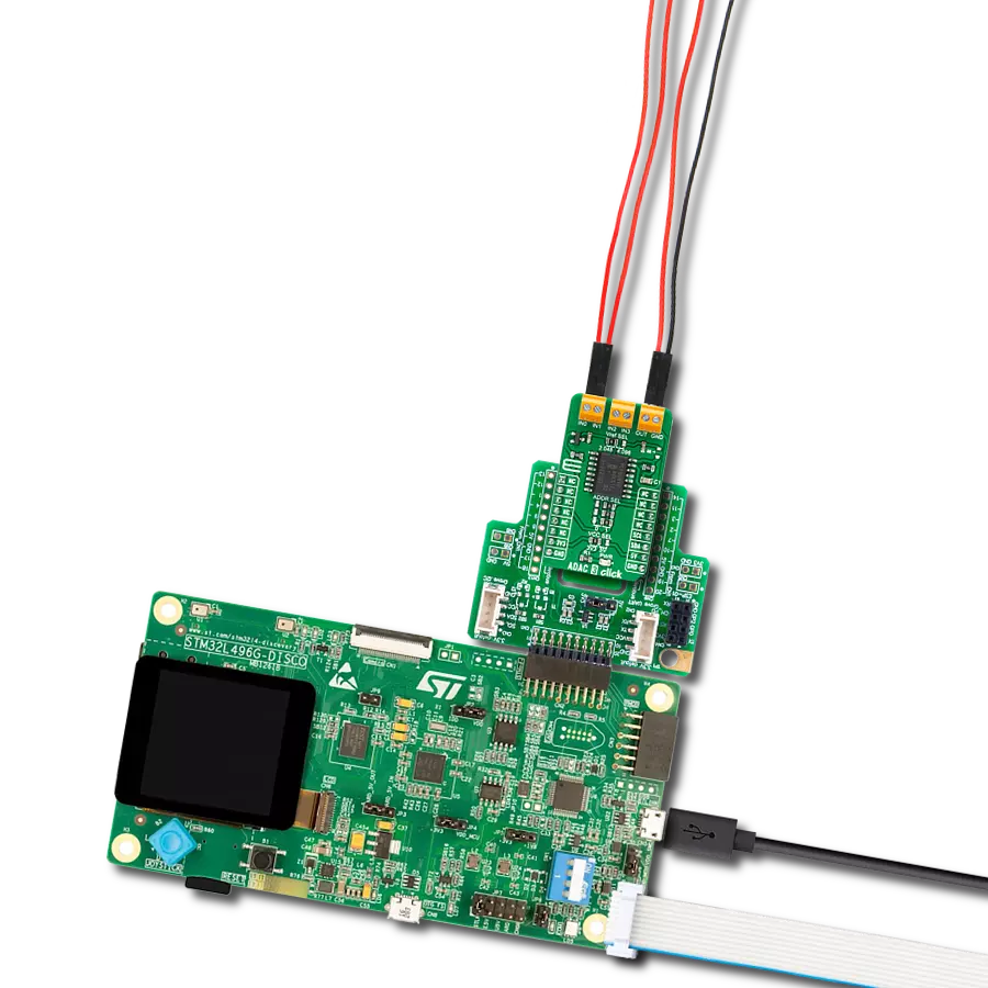
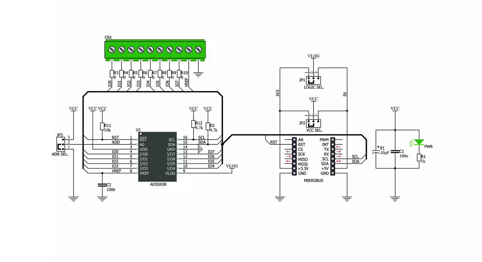
ADAC Click is based on the AD5593R, an 8-channel 12-bit ADC, DAC, and GPIO from Analog Devices. The click is designed to run on either 3.3V or 5V power supply. ADAC click communicates with the target microcontroller over the I2C interface, with additional functionality provided by the RST pin on the mikroBUS™ line. Every channel can be set individually as ADC, DAC, or GPIO.
The 12-bit conversion values are readable through I2C. The AD5593R has eight input/output (I/O) pins, which can be independently configured as digital-to-analog converter (DAC) outputs, analog-to-digital converter (ADC) inputs, digital outputs, or digital inputs. When an I/O pin is configured as an analog output, it is driven by a 12-bit DAC. The output range of the DAC is 0 V to VREF
or 0 V to 2×V REF. When an I/O pin is configured as an analog input, it is connected to a 12-bit ADC via an analog multiplexer. The input range of the ADC is 0 V to VREF or 0 V to 2 × VREF. The I/O pins can also be configured as general-purpose, digital input, or output (GPIO).

Features overview
Development board
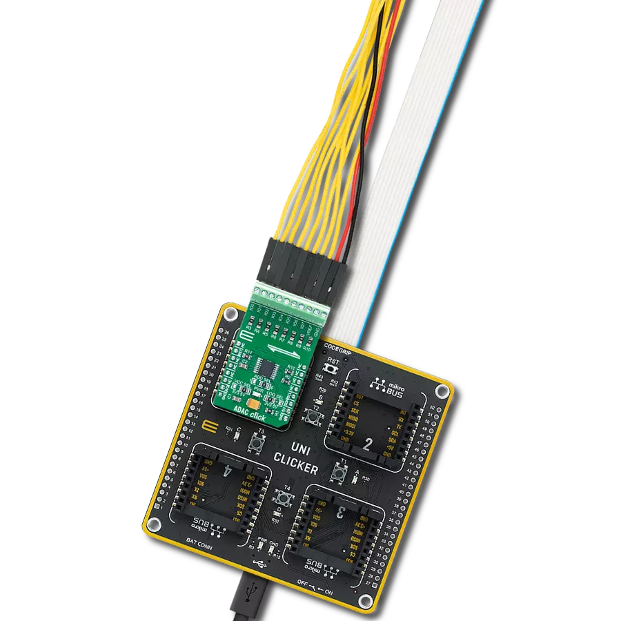
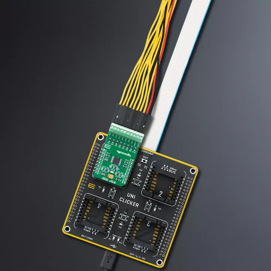
UNI Clicker is a compact development board designed as a complete solution that brings the flexibility of add-on Click boards™ to your favorite microcontroller, making it a perfect starter kit for implementing your ideas. It supports a wide range of microcontrollers, such as different ARM, PIC32, dsPIC, PIC, and AVR from various vendors like Microchip, ST, NXP, and TI (regardless of their number of pins), four mikroBUS™ sockets for Click board™ connectivity, a USB connector, LED indicators, buttons, a debugger/programmer connector, and two 26-pin headers for interfacing with external electronics. Thanks to innovative manufacturing technology, it allows you to build
gadgets with unique functionalities and features quickly. Each part of the UNI Clicker development kit contains the components necessary for the most efficient operation of the same board. In addition to the possibility of choosing the UNI Clicker programming method, using a third-party programmer or CODEGRIP/mikroProg connected to onboard JTAG/SWD header, the UNI Clicker board also includes a clean and regulated power supply module for the development kit. It provides two ways of board-powering; through the USB Type-C (USB-C) connector, where onboard voltage regulators provide the appropriate voltage levels to each component on the board, or using a Li-Po/Li
Ion battery via an onboard battery connector. All communication methods that mikroBUS™ itself supports are on this board (plus USB HOST/DEVICE), including the well-established mikroBUS™ socket, a standardized socket for the MCU card (SiBRAIN standard), and several user-configurable buttons and LED indicators. UNI Clicker is an integral part of the Mikroe ecosystem, allowing you to create a new application in minutes. Natively supported by Mikroe software tools, it covers many aspects of prototyping thanks to a considerable number of different Click boards™ (over a thousand boards), the number of which is growing every day.

Microcontroller Overview
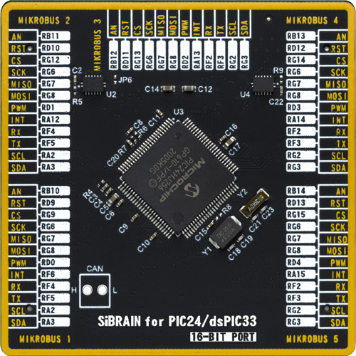
MCU Card / MCU
Type
8th Generation
Architecture
dsPIC
MCU Memory (KB)
256
Silicon Vendor
Microchip
Pin count
100
RAM (Bytes)
16384
Used MCU Pins
mikroBUS™ mapper
Take a closer look
Click board™ Schematic
Step by step
Project assembly

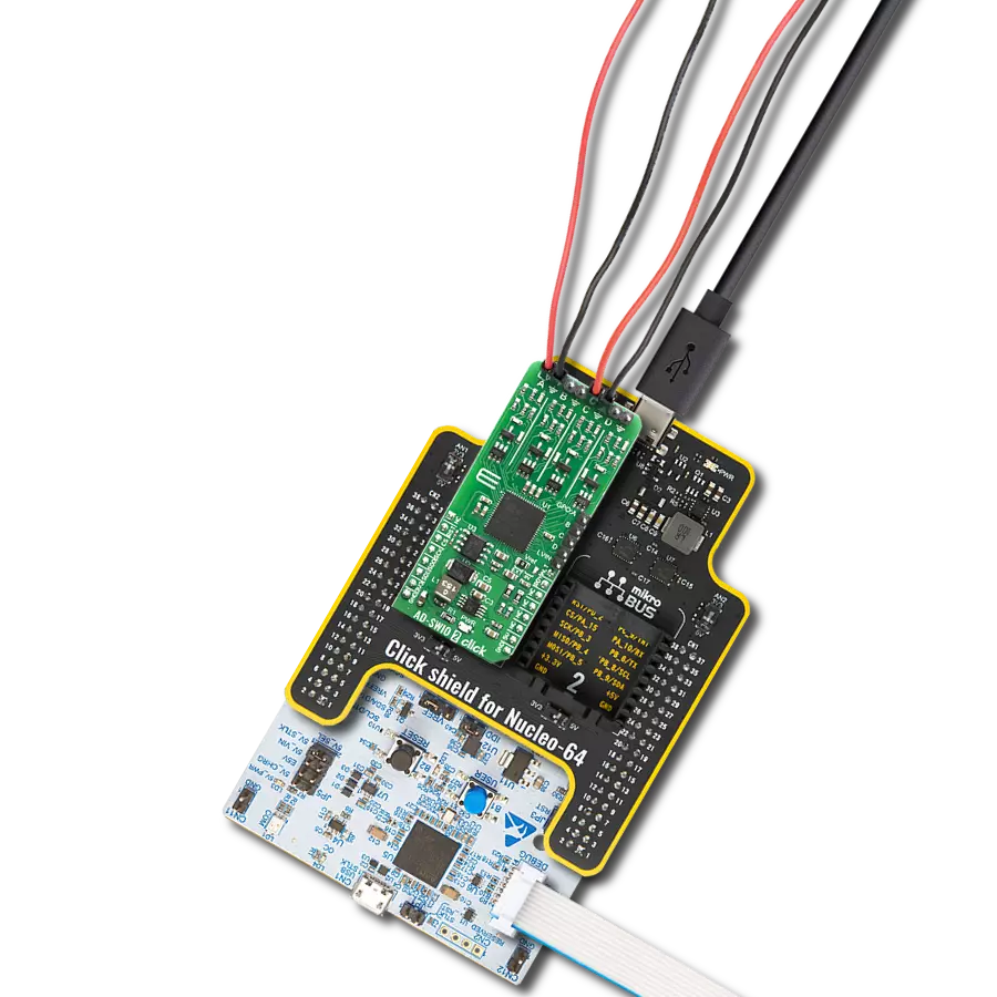
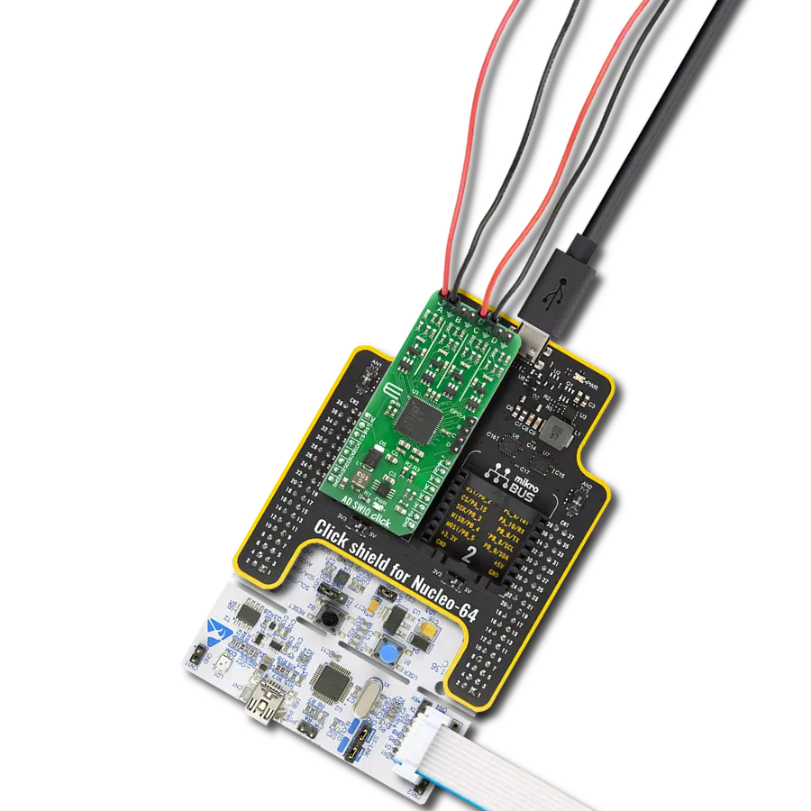
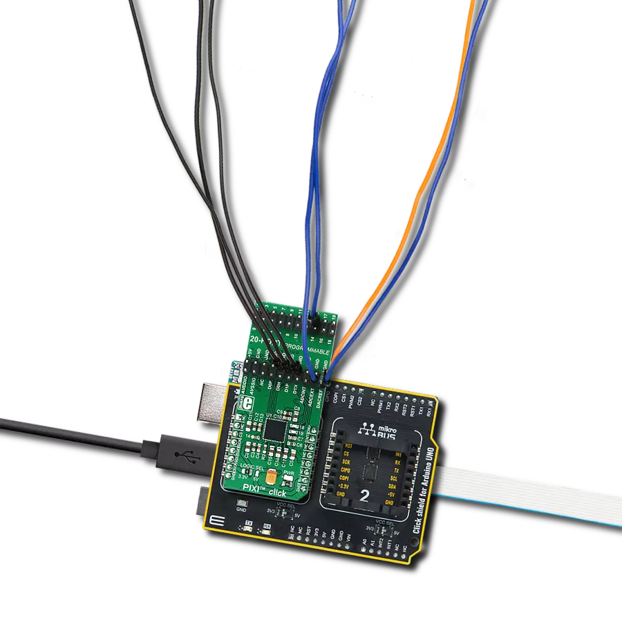
Start by selecting your development board and Click board™. Begin with the UNI Clicker as your development board.


Track your results in real time
Application Output
1. Application Output - In Debug mode, the 'Application Output' window enables real-time data monitoring, offering direct insight into execution results. Ensure proper data display by configuring the environment correctly using the provided tutorial.

2. UART Terminal - Use the UART Terminal to monitor data transmission via a USB to UART converter, allowing direct communication between the Click board™ and your development system. Configure the baud rate and other serial settings according to your project's requirements to ensure proper functionality. For step-by-step setup instructions, refer to the provided tutorial.

3. Plot Output - The Plot feature offers a powerful way to visualize real-time sensor data, enabling trend analysis, debugging, and comparison of multiple data points. To set it up correctly, follow the provided tutorial, which includes a step-by-step example of using the Plot feature to display Click board™ readings. To use the Plot feature in your code, use the function: plot(*insert_graph_name*, variable_name);. This is a general format, and it is up to the user to replace 'insert_graph_name' with the actual graph name and 'variable_name' with the parameter to be displayed.

Software Support
Library Description
ADAC Click demo application is developed using the NECTO Studio, ensuring compatibility with mikroSDK's open-source libraries and tools. Designed for plug-and-play implementation and testing, the demo is fully compatible with all development, starter, and mikromedia boards featuring a mikroBUS™ socket.
Example Description
This example showcases how to initialize, configure and use the ADAC Click module. The Click has an ADC and a DAC. An external power supply sets the maximum voltage of the input analog signal, which is bound to 2.5 V by default. For the input any external analog signal will suffice and a multimeter is needed to read the output on one of the channels.
Key functions:
adac_cfg_setup- Config Object Initialization function.adac_init- Initialization function.adac_default_cfg- Click Default Configuration function.adac_write_dac- This function writes DAC using the I2C serial interface.adac_read_adc- This function reads ADC data using the I2C serial interface.adac_set_configuration- This function sets the configuration for the Click module.
Application Init
This function initializes and configures the Click and logger modules. It does a hardware reset first and after that configures the Click module using default settings.
Application Task
This function first writes digital values ranging from 0 to 256 to output channel 3 with a 10 millisecond delay between iterations and after that reads analog values from channel 4 10 times and displays results in the UART console.
Open Source
Code example
The complete application code and a ready-to-use project are available through the NECTO Studio Package Manager for direct installation in the NECTO Studio. The application code can also be found on the MIKROE GitHub account.
/*!
 * \file
 * \brief ADAC Click example
 *
 * # Description
 * This example showcases how to initialize, configure and use the ADAC Click module. The Click
 * has an ADC and a DAC. An external power supply sets the maximum voltage of the input analog
 * signal, which is bound to 2.5 V by default. For the input any external analog signal will
 * suffice and a multimeter is needed to read the output on one of the channels.
 *
 * The demo application is composed of two sections :
 *
 * ## Application Init
 * This function initializes and configures the Click and logger modules. It does a hardware
 * reset first and after that configures the Click module using default settings.
 *
 * ## Application Task
 * This function first writes digital values ranging from 0 to 256 to output channel 3 with a
 * 10 millisecond delay between iterations and after that reads analog values from channel 4
 * 10 times and displays results in the UART console.
 *
 * \author MikroE Team
 *
 */
// ------------------------------------------------------------------- INCLUDES

#include "board.h"
#include "log.h"
#include "adac.h"

// ------------------------------------------------------------------ VARIABLES

static adac_t adac;
static log_t logger;

// ------------------------------------------------------ APPLICATION FUNCTIONS

void application_init ( )
{
    log_cfg_t log_cfg;
    adac_cfg_t cfg;

    /**
     * Logger initialization.
     * Default baud rate: 115200
     * Default log level: LOG_LEVEL_DEBUG
     * @note If USB_UART_RX and USB_UART_TX
     * are defined as HAL_PIN_NC, you will
     * need to define them manually for log to work.
     * See @b LOG_MAP_USB_UART macro definition for detailed explanation.
     */
    LOG_MAP_USB_UART( log_cfg );
    log_init( &logger, &log_cfg );
    log_info( &logger, "---- Application Init ----" );

    //  Click initialization.

    adac_cfg_setup( &cfg );
    ADAC_MAP_MIKROBUS( cfg, MIKROBUS_1 );
    adac_init( &adac, &cfg );
    Delay_ms ( 100 );
    adac_hardware_reset( &adac );
    Delay_ms ( 100 );
    adac_set_configuration( &adac, ADAC_POWER_REF_CTRL, ADAC_VREF_ON, ADAC_NO_OP );
    Delay_ms ( 100 );
    log_printf( &logger, "\r\n Click module initialized \r\n" );
    Delay_ms ( 500 );
}

void application_task ( )
{
    uint16_t adc_val;
    uint16_t cnt;
    uint8_t chan;

    log_printf( &logger, "\r\n *** DAC : write ***\r\n" );
    adac_set_configuration( &adac, ADAC_DAC_CONFIG, ADAC_NO_OP, ADAC_IO3 );
    Delay_ms ( 100 );

    for ( cnt = 0; cnt < 0xFF; cnt +=4 )
    {
        adac_write_dac( &adac, ADAC_PB_PIN3, cnt / 0x100, cnt % 0x100 );
        Delay_ms ( 10 );
        log_printf( &logger, " > write... \r\n" );
    }

    log_printf( &logger, "-------------------\r\n" );
    Delay_ms ( 1000 );

    log_printf( &logger, "\r\n *** ADC : read ***\r\n" );
    adac_set_configuration( &adac, ADAC_ADC_CONFIG, ADAC_NO_OP, ADAC_IO4 );
    Delay_ms ( 100 );
    adac_set_configuration( &adac, ADAC_ADC_SEQUENCE, ADAC_SEQUENCE_ON, ADAC_IO4 );

    for( cnt = 0; cnt < 10; cnt++ )
    {
        adc_val = adac_read_adc( &adac, &chan );
        log_printf( &logger, "   channel : %d\r\n", ( uint16_t ) chan );
        log_printf( &logger, "       val : %d\r\n", adc_val );
        Delay_ms ( 1000 );
        Delay_ms ( 1000 );
    }

    log_printf( &logger, "-------------------\r\n" );
    Delay_ms ( 1000 );
}

int main ( void )
{
    /* Do not remove this line or clock might not be set correctly. */
    #ifdef PREINIT_SUPPORTED
    preinit();
    #endif

    application_init( );

    for ( ; ; )
    {
        application_task( );
    }

    return 0;
}

// ------------------------------------------------------------------------ END
Additional Support
Resources
Category:ADC-DAC