Translate the complexity of RMS into a clear, constant DC voltage with AD8436 and STM32F415ZG
Turning RMS complexity into DC simplicity – that's our converter promise!
Published Nov 14, 2023
Click board™
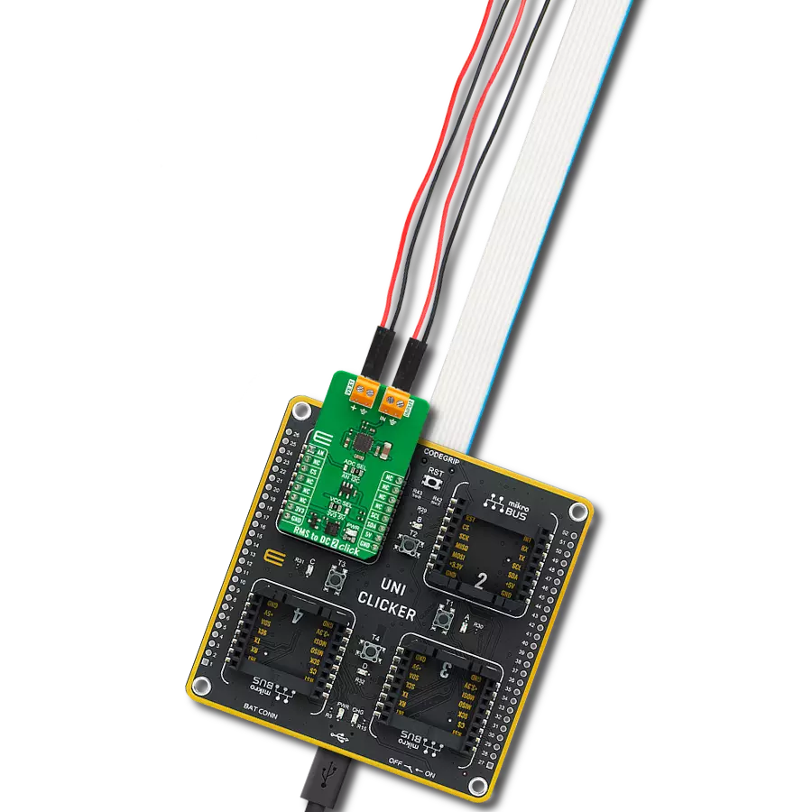
RMS to DC 2 Click
Dev. board
UNI Clicker
Compiler
NECTO Studio
MCU
STM32F415ZG
With a focus on simplicity and accuracy, our RMS-to-DC converter is the key to translating RMS input signals into a DC voltage, ensuring your measurements are both reliable and easy to interpret.
A
A
Hardware Overview
How does it work?
RMS to DC 2 Click is based on the AD8436, a low-cost, low-power, true RMS-to-DC converter from Analog Devices. It computes a precise DC equivalent of the RMS value of AC waveforms, including complex patterns such as those generated by switch mode power supplies and triacs. The accuracy conversions crest factor spans between 1 and 10. On-board buffer amplifiers enable the widest range of options, while the built-in high-impedance FET buffer provides an interface for external attenuators, frequency compensation, or driving low-impedance loads. A matched pair of internal resistors enables an easily configurable gain of two or more, extending the usable input range even lower. The RMS or Root
Mean Square describes the input signal's power: the current's RMS value equals a DC current value that would produce the same heat dissipation on the resistive load. Therefore, it is often important to know the RMS value of the signal. RMS to DC 2 Click allows measuring of the RMS value of a periodically repetitive signal. The output values of the AD8436 can be read over the analog-to-digital converter of the host MCU or over the MCP3221, a low-power 12-bit ADC from Microchip. The selection can be made over the ADC SEL jumper, where the MCP3221 is set by default. There are two terminals on RMS to DC 2 Click. The VEXT supplies the RMS core of the AD8436 with a voltage of 4.8 to 36V, while the INPUT is the AC signal input
terminal. RMS to DC 2 Click can use the analog AN pin of the mikroBUS™ socket or the I2C interface of the MCP3221 to communicate with the host MCU and read the RMS value. The default choice is the MCP3221, with its standard and fast modes of the I2C interface supporting frequencies of up to 400kHz. This Click board™ can operate with either 3.3V or 5V logic voltage levels selected via the VCC SEL jumper. This way, both 3.3V and 5V capable MCUs can use the communication lines properly. Also, this Click board™ comes equipped with a library containing easy-to-use functions and an example code that can be used as a reference for further development.

Features overview
Development board
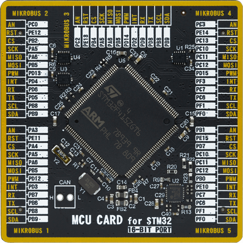
UNI Clicker is a compact development board designed as a complete solution that brings the flexibility of add-on Click boards™ to your favorite microcontroller, making it a perfect starter kit for implementing your ideas. It supports a wide range of microcontrollers, such as different ARM, PIC32, dsPIC, PIC, and AVR from various vendors like Microchip, ST, NXP, and TI (regardless of their number of pins), four mikroBUS™ sockets for Click board™ connectivity, a USB connector, LED indicators, buttons, a debugger/programmer connector, and two 26-pin headers for interfacing with external electronics. Thanks to innovative manufacturing technology, it allows you to build
gadgets with unique functionalities and features quickly. Each part of the UNI Clicker development kit contains the components necessary for the most efficient operation of the same board. In addition to the possibility of choosing the UNI Clicker programming method, using a third-party programmer or CODEGRIP/mikroProg connected to onboard JTAG/SWD header, the UNI Clicker board also includes a clean and regulated power supply module for the development kit. It provides two ways of board-powering; through the USB Type-C (USB-C) connector, where onboard voltage regulators provide the appropriate voltage levels to each component on the board, or using a Li-Po/Li
Ion battery via an onboard battery connector. All communication methods that mikroBUS™ itself supports are on this board (plus USB HOST/DEVICE), including the well-established mikroBUS™ socket, a standardized socket for the MCU card (SiBRAIN standard), and several user-configurable buttons and LED indicators. UNI Clicker is an integral part of the Mikroe ecosystem, allowing you to create a new application in minutes. Natively supported by Mikroe software tools, it covers many aspects of prototyping thanks to a considerable number of different Click boards™ (over a thousand boards), the number of which is growing every day.

Microcontroller Overview
MCU Card / MCU
Type
8th Generation
Architecture
ARM Cortex-M4
MCU Memory (KB)
1024
Silicon Vendor
STMicroelectronics
Pin count
144
RAM (Bytes)
196608
Used MCU Pins
mikroBUS™ mapper
Take a closer look
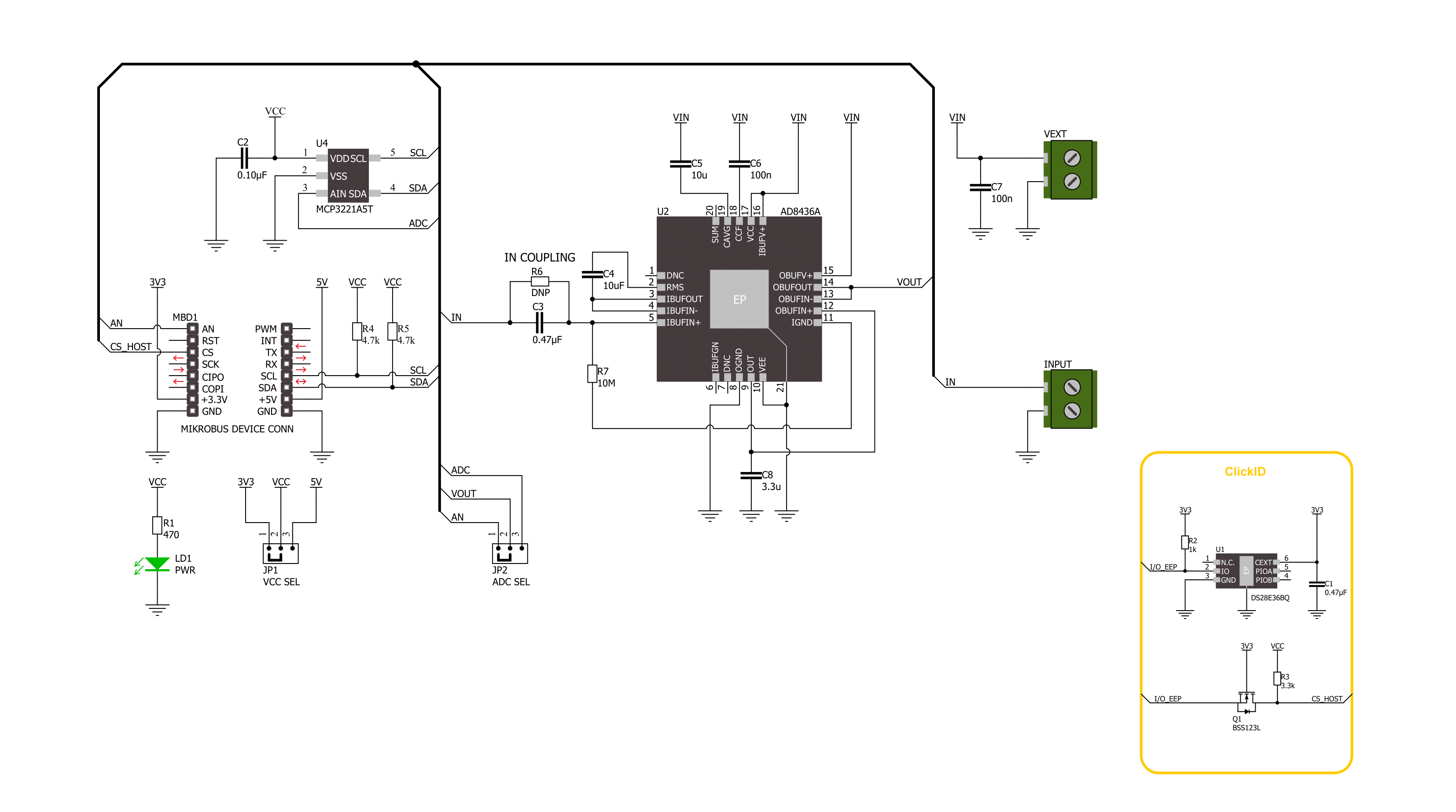
Click board™ Schematic
Step by step
Project assembly

Start by selecting your development board and Click board™. Begin with the UNI Clicker as your development board.


Track your results in real time
Application Output
1. Application Output - In Debug mode, the 'Application Output' window enables real-time data monitoring, offering direct insight into execution results. Ensure proper data display by configuring the environment correctly using the provided tutorial.

2. UART Terminal - Use the UART Terminal to monitor data transmission via a USB to UART converter, allowing direct communication between the Click board™ and your development system. Configure the baud rate and other serial settings according to your project's requirements to ensure proper functionality. For step-by-step setup instructions, refer to the provided tutorial.

3. Plot Output - The Plot feature offers a powerful way to visualize real-time sensor data, enabling trend analysis, debugging, and comparison of multiple data points. To set it up correctly, follow the provided tutorial, which includes a step-by-step example of using the Plot feature to display Click board™ readings. To use the Plot feature in your code, use the function: plot(*insert_graph_name*, variable_name);. This is a general format, and it is up to the user to replace 'insert_graph_name' with the actual graph name and 'variable_name' with the parameter to be displayed.

Software Support
Library Description
This library contains API for RMS to DC 2 Click driver.
Key functions:
rmstodc2_set_vref- This function sets the voltage reference for RMS to DC 2 click driver.rmstodc2_read_voltage- This function reads raw ADC value and converts it to proportional voltage level.
Open Source
Code example
The complete application code and a ready-to-use project are available through the NECTO Studio Package Manager for direct installation in the NECTO Studio. The application code can also be found on the MIKROE GitHub account.
/*!
 * @file main.c
 * @brief RMS to DC 2 Click Example.
 *
 * # Description
 * This example demonstrates the use of the RMS to DC 2 Click board by measuring
 * the RMS voltage of the input signal.
 *
 * The demo application is composed of two sections :
 *
 * ## Application Init
 * Initializes the driver and logger.
 *
 * ## Application Task
 * Reads the RMS voltage of the input signal and displays the results on the USB UART
 * approximately once per second.
 *
 * @author Stefan Filipovic
 *
 */

#include "board.h"
#include "log.h"
#include "rmstodc2.h"

static rmstodc2_t rmstodc2;   /**< RMS to DC 2 Click driver object. */
static log_t logger;    /**< Logger object. */

void application_init ( void )
{
    log_cfg_t log_cfg;  /**< Logger config object. */
    rmstodc2_cfg_t rmstodc2_cfg;  /**< Click config object. */

    /**
     * Logger initialization.
     * Default baud rate: 115200
     * Default log level: LOG_LEVEL_DEBUG
     * @note If USB_UART_RX and USB_UART_TX
     * are defined as HAL_PIN_NC, you will
     * need to define them manually for log to work.
     * See @b LOG_MAP_USB_UART macro definition for detailed explanation.
     */
    LOG_MAP_USB_UART( log_cfg );
    log_init( &logger, &log_cfg );
    log_info( &logger, " Application Init " );

    // Click initialization.
    rmstodc2_cfg_setup( &rmstodc2_cfg );
    RMSTODC2_MAP_MIKROBUS( rmstodc2_cfg, MIKROBUS_1 );
    err_t init_flag = rmstodc2_init( &rmstodc2, &rmstodc2_cfg );
    if ( ( ADC_ERROR == init_flag ) || ( I2C_MASTER_ERROR == init_flag ) )
    {
        log_error( &logger, " Communication init." );
        for ( ; ; );
    }

    log_info( &logger, " Application Task " );
}

void application_task ( void )
{
    float voltage = 0;
    if ( RMSTODC2_OK == rmstodc2_read_voltage ( &rmstodc2, &voltage ) )
    {
        log_printf( &logger, " RMS voltage : %.3f[V]\r\n\n", voltage * RMSTODC2_RMS_VOLTAGE_COEF );
        Delay_ms ( 1000 );
    }
}

int main ( void )
{
    /* Do not remove this line or clock might not be set correctly. */
    #ifdef PREINIT_SUPPORTED
    preinit();
    #endif

    application_init( );

    for ( ; ; )
    {
        application_task( );
    }

    return 0;
}

// ------------------------------------------------------------------------ END


