Safeguard your devices and elevate their performance with STPW12 and STM32F042C6
Effortless power management: Elevate performance with eFuse excellence

Published Oct 09, 2023
Click board™
eFuse Click
Dev. board
UNI Clicker
Compiler
NECTO Studio
MCU
STM32F042C6
Our vision is to empower your devices with eFuse precision, setting the standard for future power control solutions, and ensuring optimal performance and control
A
A
Hardware Overview
How does it work?
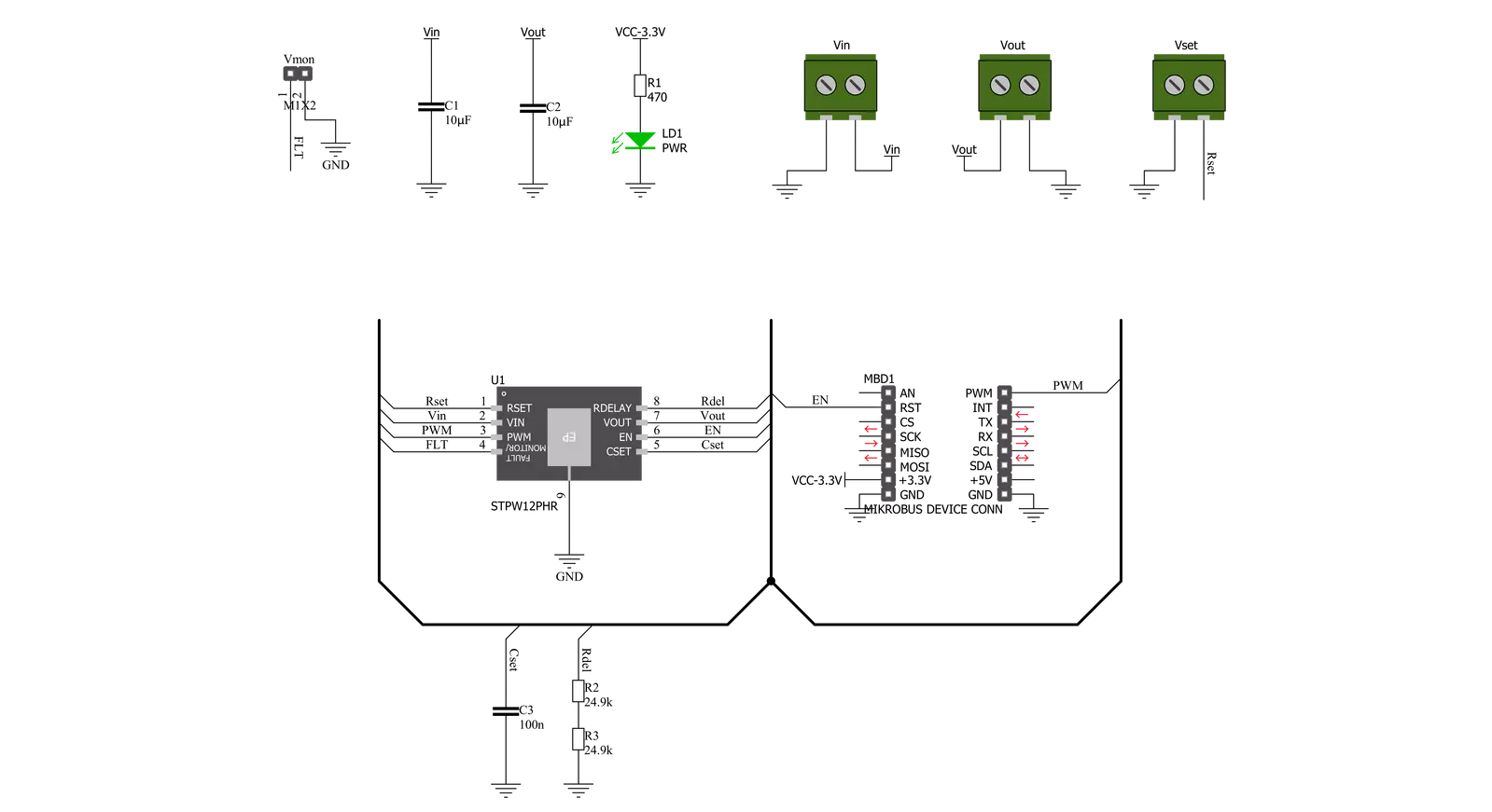
eFuse Click is based on the STPW12, a programmable electronic power breaker optimized to monitor the input power from STMicroelectronics. The device is designed and optimized to work on 12V power rails, even if the operating supply voltage can range from 10.5V to 18V. Connected in series to the power rail, it can disconnect the electronic circuitry on its output if the power consumption overcomes the programmed limit. The intervention threshold is programmed by the resistor connected to the RSET terminal. When this happens, the STPW12 automatically opens the integrated power switch and disconnects the load. The overcoming of the power limit threshold is signaled on the monitor/fault pin on the onboard header pin
labeled VMON. The monitor/fault pin is proportional to the power, continuously present on the pin, and provides two valuable signals for the real-time control of the device and application status. After a particular delay time, programmable by the user, the STPW12 automatically tries again to close the internal switch and re-connect the load. eFuse Click communicates with MCU using two GPIO pins routed on the PWM and RST pins of the mikroBUS™ socket labeled PWM and EN. The device can be turned on or off through a dedicated Enable (EN) pin with a direct PWM mode, which can be achieved through an external PWM signal. In this mode, the device's internal power switch can be driven ON/OFF by an external
PWM signal provided to the PWM pin of the STPW12 (square wave, maximum 2kHz, duty cycle 20% - 100%). This approach allows the user to optimize the design power distribution system in terms of accurate power control, choice of isolation material, and safety improvements, such as the reduced risk of flammability and easier qualification and certification flow. This Click board™ can be operated only with a 3.3V logic voltage level. The board must perform appropriate logic voltage level conversion before using MCUs with different logic levels. Also, it comes equipped with a library containing functions and an example code that can be used as a reference for further development.

Features overview
Development board
UNI Clicker is a compact development board designed as a complete solution that brings the flexibility of add-on Click boards™ to your favorite microcontroller, making it a perfect starter kit for implementing your ideas. It supports a wide range of microcontrollers, such as different ARM, PIC32, dsPIC, PIC, and AVR from various vendors like Microchip, ST, NXP, and TI (regardless of their number of pins), four mikroBUS™ sockets for Click board™ connectivity, a USB connector, LED indicators, buttons, a debugger/programmer connector, and two 26-pin headers for interfacing with external electronics. Thanks to innovative manufacturing technology, it allows you to build
gadgets with unique functionalities and features quickly. Each part of the UNI Clicker development kit contains the components necessary for the most efficient operation of the same board. In addition to the possibility of choosing the UNI Clicker programming method, using a third-party programmer or CODEGRIP/mikroProg connected to onboard JTAG/SWD header, the UNI Clicker board also includes a clean and regulated power supply module for the development kit. It provides two ways of board-powering; through the USB Type-C (USB-C) connector, where onboard voltage regulators provide the appropriate voltage levels to each component on the board, or using a Li-Po/Li
Ion battery via an onboard battery connector. All communication methods that mikroBUS™ itself supports are on this board (plus USB HOST/DEVICE), including the well-established mikroBUS™ socket, a standardized socket for the MCU card (SiBRAIN standard), and several user-configurable buttons and LED indicators. UNI Clicker is an integral part of the Mikroe ecosystem, allowing you to create a new application in minutes. Natively supported by Mikroe software tools, it covers many aspects of prototyping thanks to a considerable number of different Click boards™ (over a thousand boards), the number of which is growing every day.

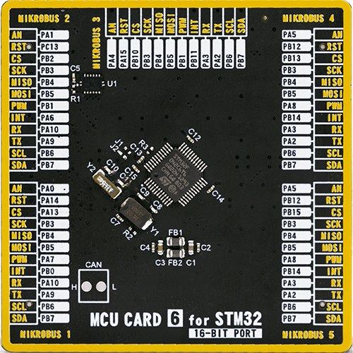
Microcontroller Overview
MCU Card / MCU
Type
8th Generation
Architecture
ARM Cortex-M0
MCU Memory (KB)
32
Silicon Vendor
STMicroelectronics
Pin count
48
RAM (Bytes)
6144
Used MCU Pins
mikroBUS™ mapper
Take a closer look
Click board™ Schematic
Step by step
Project assembly

Start by selecting your development board and Click board™. Begin with the UNI Clicker as your development board.


Software Support
Library Description
This library contains API for eFuse Click driver.
Key functions:
efuse_enable_device- eFuse enable the device functionefuse_disable_device- eFuse disable the device functionefuse_disable_pwm- eFuse disable the device function
Open Source
Code example
The complete application code and a ready-to-use project are available through the NECTO Studio Package Manager for direct installation in the NECTO Studio. The application code can also be found on the MIKROE GitHub account.
/*!
 * @file main.c
 * @brief eFuse Click Example.
 *
 * # Description
 * This library contains API for the eFuse Click driver.
 * This demo application shows use of a eFuse Click board™.
 *
 * The demo application is composed of two sections :
 *
 * ## Application Init
 * Initialization of GPIO module and log UART.
 * After driver initialization the app set default settings.
 *
 * ## Application Task
 * This is an example that shows the use of an eFuse Click board™.
 * The Electronic Fuse is an electrical safety device that operates to
 * provide overcurrent protection of an electrical circuit.
 * The intervention threshold is programmed by the Rs resistor.
 * The device disconnects the load if the power overcomes the pre-set threshold,
 * for example if Vset = 3.9 kOhm, Vin = 12 V,
 * the intervention threshold is set approximately to 875 mA.
 * Results are being sent to the Usart Terminal where you can track their changes.
 *
 * @author Nenad Filipovic
 *
 */

#include "board.h"
#include "log.h"
#include "efuse.h"

static efuse_t efuse;   /**< eFuse Click driver object. */
static log_t logger;    /**< Logger object. */

void application_init ( void )
{
    log_cfg_t log_cfg;      /**< Logger config object. */
    efuse_cfg_t efuse_cfg;  /**< Click config object. */

    /**
     * Logger initialization.
     * Default baud rate: 115200
     * Default log level: LOG_LEVEL_DEBUG
     * @note If USB_UART_RX and USB_UART_TX
     * are defined as HAL_PIN_NC, you will
     * need to define them manually for log to work.
     * See @b LOG_MAP_USB_UART macro definition for detailed explanation.
     */
    LOG_MAP_USB_UART( log_cfg );
    log_init( &logger, &log_cfg );
    log_info( &logger, " Application Init " );

    // Click initialization.

    efuse_cfg_setup( &efuse_cfg );
    EFUSE_MAP_MIKROBUS( efuse_cfg, MIKROBUS_1 );
    if ( efuse_init( &efuse, &efuse_cfg ) == DIGITAL_OUT_UNSUPPORTED_PIN )
    {
        log_error( &logger, " Application Init Error. " );
        log_info( &logger, " Please, run program again... " );

        for ( ; ; );
    }
    efuse_default_cfg ( &efuse );
    Delay_ms ( 100 );

    log_printf( &logger, " Disable PWM \r\n" );
    efuse_disable_pwm( &efuse );
    Delay_ms ( 100 );

    log_info( &logger, " Application Task " );
    Delay_ms ( 100 );
}

void application_task ( void )
{
    log_printf( &logger, "--------------------------\r\n" );
    log_printf( &logger, "\t Active \r\n" );
    efuse_enable_device( &efuse );
    // 10 seconds delay
    Delay_ms ( 1000 );
    Delay_ms ( 1000 );
    Delay_ms ( 1000 );
    Delay_ms ( 1000 );
    Delay_ms ( 1000 );
    Delay_ms ( 1000 );
    Delay_ms ( 1000 );
    Delay_ms ( 1000 );
    Delay_ms ( 1000 );
    Delay_ms ( 1000 );

    log_printf( &logger, "--------------------------\r\n" );
    log_printf( &logger, "\tInactive \r\n" );
    efuse_disable_device( &efuse );
    // 10 seconds delay
    Delay_ms ( 1000 );
    Delay_ms ( 1000 );
    Delay_ms ( 1000 );
    Delay_ms ( 1000 );
    Delay_ms ( 1000 );
    Delay_ms ( 1000 );
    Delay_ms ( 1000 );
    Delay_ms ( 1000 );
    Delay_ms ( 1000 );
    Delay_ms ( 1000 );
}

int main ( void )
{
    /* Do not remove this line or clock might not be set correctly. */
    #ifdef PREINIT_SUPPORTED
    preinit();
    #endif

    application_init( );

    for ( ; ; )
    {
        application_task( );
    }

    return 0;
}

// ------------------------------------------------------------------------ END


