Bring unprecedented accuracy and versatility to voltage control with MCP4361 and PIC18F47Q10
Ohm-inous possibilities
Published Aug 21, 2023
Click board™
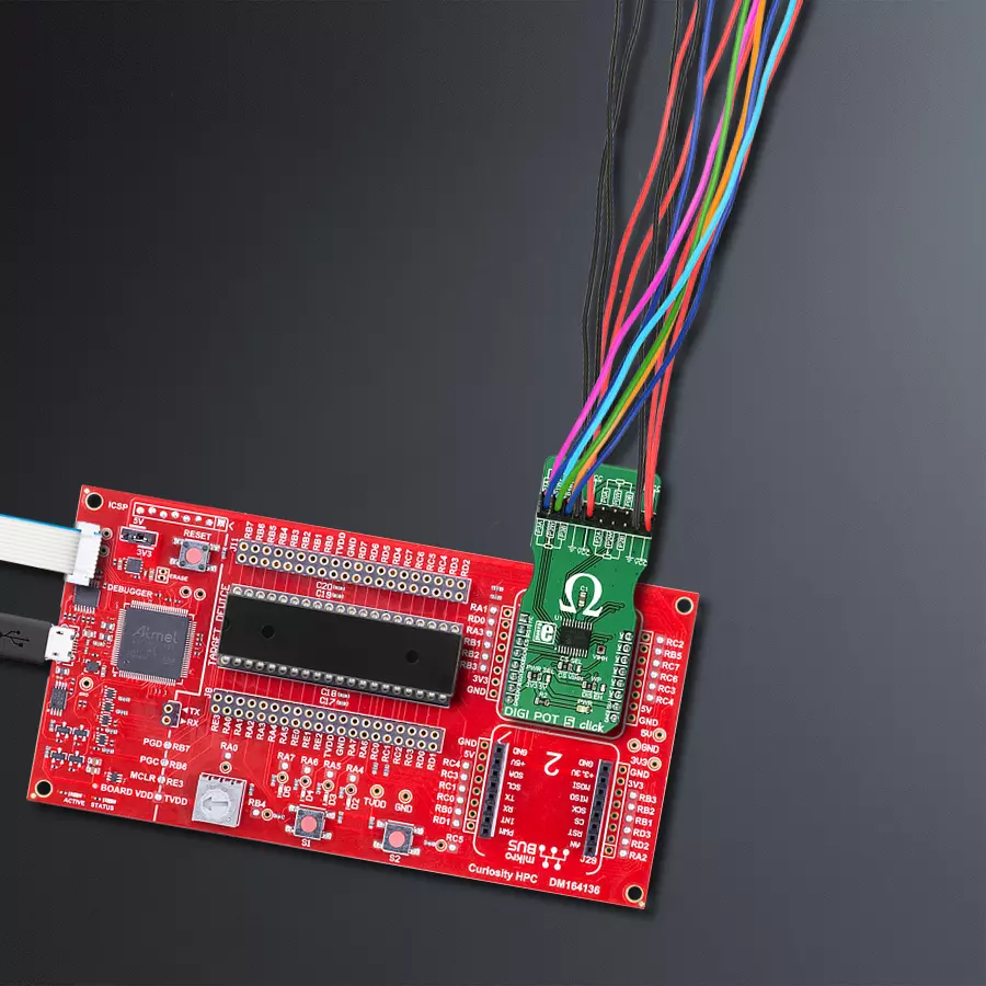
DIGI POT 5 click
Dev. board
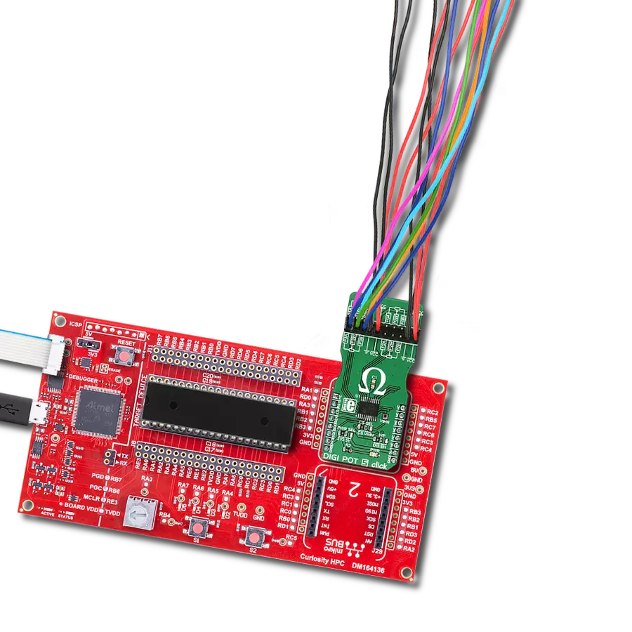
Curiosity HPC
Compiler
NECTO Studio
MCU
PIC18F47Q10
Replace cumbersome mechanical potentiometers with our digital alternative, improving reliability, durability, and allowing for advanced automation
A
A
Hardware Overview
How does it work?
DIGI POT 5 Click is based on the MCP4361, an 8-bit quad digital potentiometer from Microchip. This is a very versatile quad-digital potentiometer controlled via the SPI interface. The device has four integrated digital potentiometer sections, which consist of a string of resistors - serially connected, with digitally controlled analog switches, used to connect the wiper terminal position. The wiper position value of 0x000h corresponds to the lower end of the resistor ladder, while 0x100h corresponds to the upper end. These values can be written in the volatile wiper registers, with one address for each of the four wipers. Each of the four wipers can be controlled in several ways. Writing data directly to the volatile wiper register will move the wiper to the specified location. Wiper value can also be incremented or decremented by writing data to the incrementing or decrementing registers, providing that the wiper is not locked and that the wiper register value is not 0x000h (prevents further decrease) or above 0x100h (prevents further increase). Increasing and decreasing commands will be disregarded if the wiper register is set to a value greater than 0x100h. The incrementing and decrementing registers allow for less overhead if the wiper position has to be increased or decreased, making it easy to interface with the
rotary encoder applications, for example. The MCP4361 also features the WiperLock™ function, which prevents further changes in the wiper position, effectively locking the wiper in place. The CS pin must be pulled beyond the predefined voltage level threshold (8.5V to 12.5V) to enable this functionality. When this happens, the device enters the high voltage communication mode (HV mode), and the WiperLock™ functions can be accessed. The click board has a dedicated high-voltage input pad (VIHH), which can drive the CS pin with the appropriate voltage level when the HV mode is required. The resistor ladder network can be completely turned off by writing to the terminal control registers. This effectively disconnects the potentiometer terminals from a circuit, reducing the power consumption of the MCP4361 and the electrical circuit the IC is used in. The terminal control registers can switch the wiper terminals and the two resistor terminals separately. A STATUS register is also used for storing various status-related information, such as the WiperLock™ status, EEPROM writes to protect the status, and so on. The EEPROM memory holds the wiper data, even after the power is down. Several (five) general purpose 9bit addresses and 4 NV wiper register addresses are copied to the wiper register addresses after the restart or
power-up, allowing the device to resume the wiper position from a previous, stored state. By default, the data registers are zeroed out, while the NV wiper registers hold the middle scale position for the wiper. DIGI POT 5 Click has one 2x10 pin standard, 2.54mm pitch header connecting the four potentiometer terminals. There are three SMD jumpers onboard: The SMD jumper labeled WP is used to set the WP pin state of the MCP4361. The WP pin is used as the hardware EEPROM write protection and a software WP bit of the STATUS register (writable in HV mode only). The hardware WP pin and the software WP bit must be set to disabled mode to write to EEPROM. The SMD jumper labeled PWR SEL selects the power supply voltage - 3.3V or 5V. This also affects the logic voltage levels used for the SPI communication. The SMD jumper labeled CS SEL selects the CS pin voltage level. If the HV mode is required, this jumper should be moved to the VIHH position so that the externally connected 8.5V to 12.5V power source can pull up the CS pin. If HV mode is not required, this SMD jumper should stay at the default position (CS). Note that while in the HV mode, the CS pin is used the same way as with the regular SPI communication, with a difference in logical levels - the HV mode logical HIGH is at least 8.5V.

Features overview
Development board
Curiosity HPC, standing for Curiosity High Pin Count (HPC) development board, supports 28- and 40-pin 8-bit PIC MCUs specially designed by Microchip for the needs of rapid development of embedded applications. This board has two unique PDIP sockets, surrounded by dual-row expansion headers, allowing connectivity to all pins on the populated PIC MCUs. It also contains a powerful onboard PICkit™ (PKOB), eliminating the need for an external programming/debugging tool, two mikroBUS™ sockets for Click board™ connectivity, a USB connector, a set of indicator LEDs, push button switches and a variable potentiometer. All
these features allow you to combine the strength of Microchip and Mikroe and create custom electronic solutions more efficiently than ever. Each part of the Curiosity HPC development board contains the components necessary for the most efficient operation of the same board. An integrated onboard PICkit™ (PKOB) allows low-voltage programming and in-circuit debugging for all supported devices. When used with the MPLAB® X Integrated Development Environment (IDE, version 3.0 or higher) or MPLAB® Xpress IDE, in-circuit debugging allows users to run, modify, and troubleshoot their custom software and hardware
quickly without the need for additional debugging tools. Besides, it includes a clean and regulated power supply block for the development board via the USB Micro-B connector, alongside all communication methods that mikroBUS™ itself supports. Curiosity HPC development board allows you to create a new application in just a few steps. Natively supported by Microchip software tools, it covers many aspects of prototyping thanks to many number of different Click boards™ (over a thousand boards), the number of which is growing daily.

Microcontroller Overview
MCU Card / MCU
Architecture
PIC
MCU Memory (KB)
128
Silicon Vendor
Microchip
Pin count
40
RAM (Bytes)
3615
Used MCU Pins
mikroBUS™ mapper
Take a closer look
Click board™ Schematic

Step by step
Project assembly

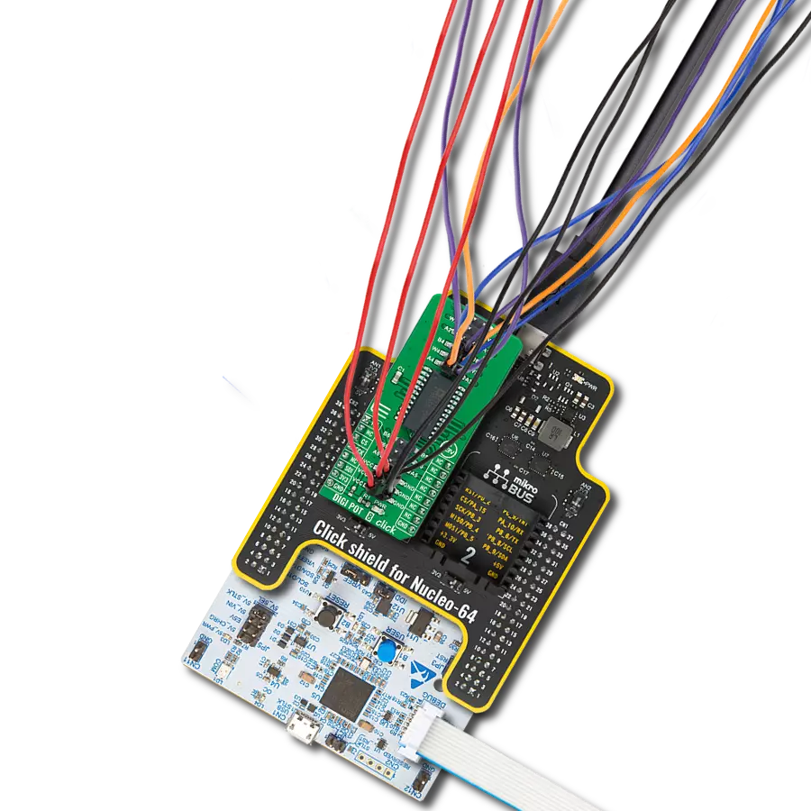
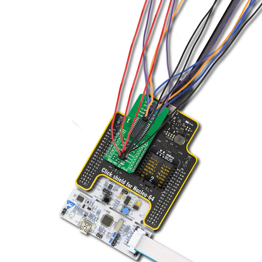
Start by selecting your development board and Click board™. Begin with the Curiosity HPC as your development board.


Software Support
Library Description
This library contains API for DIGI POT 5 Click driver.
Key functions:
digipot5_generic_write- Generic Write functiondigipot5_generic_read- Generic Read functiondigipot5_increment_wiper- Increment Wiper function
Open Source
Code example
The complete application code and a ready-to-use project are available through the NECTO Studio Package Manager for direct installation in the NECTO Studio. The application code can also be found on the MIKROE GitHub account.
/*!
 * \file main.c
 * \brief DIGI POT 5 Click example
 *
 * # Description
 * This example demonstrates the use of the DIGI POT 5 Click board.
 *
 * The demo application is composed of two sections :
 *
 * ## Application Init
 * Initializes all necessary peripherals and pins used for the DIGI POT 5 Click.
 * Also allows the device to be reset and configured to enable all wipers (4).
 * UART console module will be initialized also in this function.
 *
 * ## Application Task
 * Demonstrates the use of Click driver functions by performing a control of
 * the all wipers positions. By checking the uart console, user can be informed
 * about the all current wipers positions.
 *
 * *note:*
 * Increment/decrement command can be issued only to volatile wiper locations.
 *
 * \author Nemanja Medakovic
 *
 */
// ------------------------------------------------------------------- INCLUDES

#include "board.h"
#include "log.h"
#include "digipot5.h"


// ------------------------------------------------------------------ VARIABLES

static digipot5_t digipot5;
static log_t console;
static uint8_t i;

// ------------------------------------------------------ APPLICATION FUNCTIONS

void application_init( void )
{
    digipot5_cfg_t digipot5_cfg;
    log_cfg_t console_cfg;

    //  Click initialization.
    digipot5_cfg_setup( &digipot5_cfg );
    DIGIPOT5_MAP_MIKROBUS( digipot5_cfg, MIKROBUS_1 );
    digipot5_init( &digipot5, &digipot5_cfg );
    digipot5_reset( &digipot5 );
    digipot5_default_cfg( &digipot5 );

    /**
     * Logger initialization.
     * Default baud rate: 115200
     * Default log level: LOG_LEVEL_DEBUG
     * @note If USB_UART_RX and USB_UART_TX
     * are defined as HAL_PIN_NC, you will
     * need to define them manually for log to work.
     * See @b LOG_MAP_USB_UART macro definition for detailed explanation.
     */
    LOG_MAP_USB_UART( console_cfg );
    log_init( &console, &console_cfg );
    log_printf( &console, "***  DIGI POT 5 Initialization Done  ***\r\n" );
    log_printf( &console, "****************************************\r\n" );
}

void application_task( void )
{
    log_printf( &console, "* Setting wiper 0 to zero scale.\r\n" );
    digipot5_generic_write( &digipot5, DIGIPOT5_REG_WIPER0_VOL,
                            DIGIPOT5_RES_ZEROSCALE );
    log_printf( &console, "* Setting wiper 1 to 3k Ohm.\r\n" );
    digipot5_generic_write( &digipot5, DIGIPOT5_REG_WIPER1_VOL,
                            DIGIPOT5_RES_3KOHM );
    log_printf( &console, "* Setting wiper 2 to half scale (5k Ohm).\r\n" );
    digipot5_generic_write( &digipot5, DIGIPOT5_REG_WIPER2_VOL,
                            DIGIPOT5_RES_5KOHM_HALFSCALE );
    log_printf( &console, "* Setting wiper 3 to full scale (10k Ohm).\r\n" );
    digipot5_generic_write( &digipot5, DIGIPOT5_REG_WIPER3_VOL,
                            DIGIPOT5_RES_10KOHM_FULLSCALE );

    Delay_ms ( 1000 );
    Delay_ms ( 1000 );
    Delay_ms ( 1000 );
    log_printf( &console, "* Decrementing wiper 3 by 5 steps.\r\n" );
    for ( i = 0; i < 5; i++ )
    {
        digipot5_decrement_wiper( &digipot5, DIGIPOT5_REG_WIPER3_VOL );
    }

    Delay_ms ( 1000 );
    Delay_ms ( 1000 );
    Delay_ms ( 1000 );
    log_printf( &console, "* Incrementing wiper 0 by 10 steps.\r\n" );
    for ( i = 0; i < 10; i++ )
    {
        digipot5_increment_wiper( &digipot5, DIGIPOT5_REG_WIPER0_VOL );
    }

    Delay_ms ( 1000 );
    Delay_ms ( 1000 );
    Delay_ms ( 1000 );
    log_printf( &console, "* Setting wiper 0 to 2k Ohm.\r\n" );
    digipot5_generic_write( &digipot5, DIGIPOT5_REG_WIPER0_VOL,
                            DIGIPOT5_RES_2KOHM );
    log_printf( &console, "* Setting wiper 1 to 2k Ohm.\r\n" );
    digipot5_generic_write( &digipot5, DIGIPOT5_REG_WIPER1_VOL,
                            DIGIPOT5_RES_2KOHM );
    log_printf( &console, "* Setting wiper 2 to 2k Ohm.\r\n" );
    digipot5_generic_write( &digipot5, DIGIPOT5_REG_WIPER2_VOL,
                            DIGIPOT5_RES_2KOHM );
    log_printf( &console, "* Setting wiper 3 to 2k Ohm.\r\n" );
    digipot5_generic_write( &digipot5, DIGIPOT5_REG_WIPER3_VOL,
                            DIGIPOT5_RES_2KOHM );

    Delay_ms ( 1000 );
    Delay_ms ( 1000 );
    Delay_ms ( 1000 );
    log_printf( &console, "****************************************\r\n" );
}

int main ( void )
{
    /* Do not remove this line or clock might not be set correctly. */
    #ifdef PREINIT_SUPPORTED
    preinit();
    #endif

    application_init( );

    for ( ; ; )
    {
        application_task( );
    }

    return 0;
}


// ------------------------------------------------------------------------ END
Additional Support
Resources
Category:Digital potentiometer