Take control of the air you breathe using MiCS-6814 and PIC18F4620
Take a deep breath comfortably
Published Nov 01, 2023
Click board™
Air quality 5 Click
Dev. board
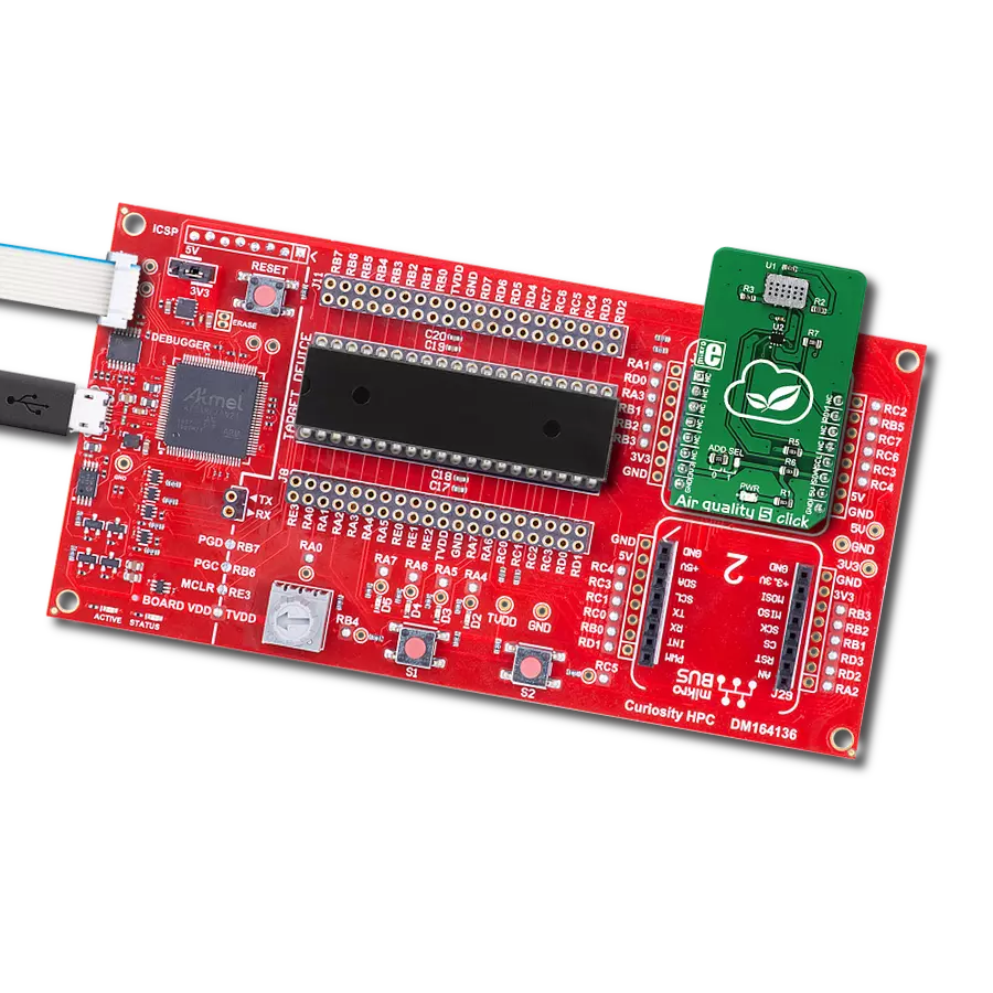
Curiosity HPC
Compiler
NECTO Studio
MCU
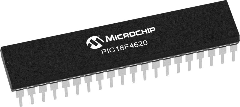
PIC18F4620
With real-time alerts and actionable insights, our monitor solution transforms air quality management into a dynamic and responsive process for safer living
A
A
Hardware Overview
How does it work?
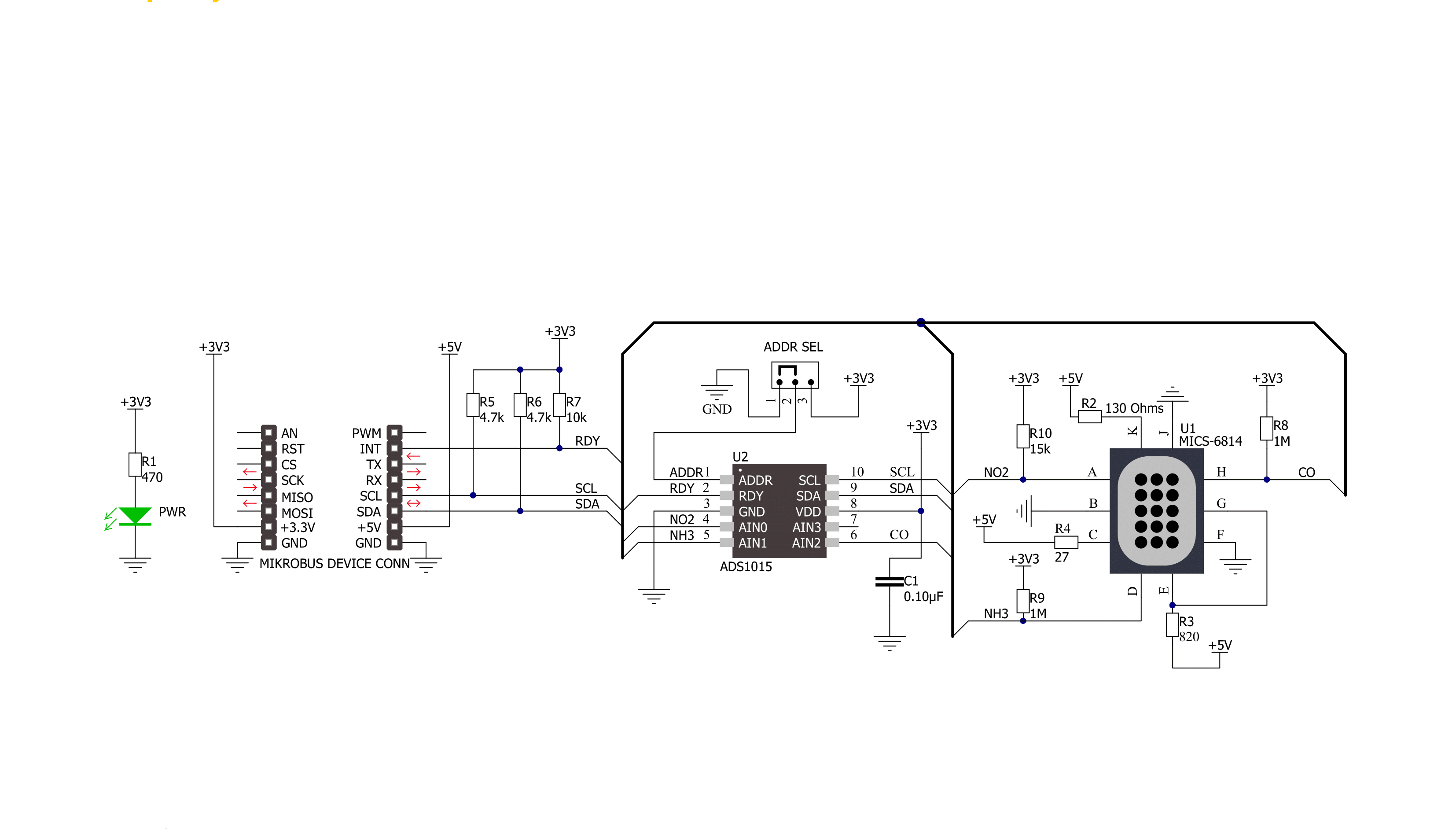
Air Quality 5 Click is based on the MiCS-6814, a compact triple MOS sensor from SGX Sensortech with three fully independent sensors. The Click board™ also contains the ADS1015, a low-power 12-bit ADC with Internal reference and a programmable comparator from Texas Instruments. The MiCS-6814 sensor comprises three independent metal oxide sensors heated by three separate heater structures. Chemicals absorbed by the metal oxide surface change the resistive properties of the sensor. The typical baseline resistance may vary a lot from sensor to sensor, which can be affected by the measurement conditions, sensor aging, and several other factors. Therefore, it is recommended to periodically monitor the relative change of the sensing resistance against the baseline resistance. It allows the development of applications that detect relative gas concentration changes rather than measuring the absolute gas concentration values. As mentioned, there are three sensors on
the same die. Each of them reacts with a different type of gas. There is a RED sensor, which reacts with the reducing gas agents, an OX sensor, which reacts with the oxidizing gas agents, and a sensor that reacts with NH3. These sensors provide readings (in ppm) for eight different gasses, which are interesting to monitor in the automotive, industry, or agriculture-polluted atmosphere. Every heating structure is powered from the mikroBUS™ 5V power rail via the resistor recommended by the manufacturer. This ensures the maximum life cycle of the device is achieved since current ratings above the recommended would damage the sensors and heaters. It is recommended to pre-heat the sensors for at least 30 seconds before valid readings can be made. The longer the pre-heat period is, the more accurate the measurement becomes. The changes in the sensor resistance are measured and sampled by the onboard ADC. The ADS1015 ADC has four multiplexed inputs, of which three are
connected to each sensor. The ADC has an internal reference, is simple to operate, offers inputs that can handle voltages across the sensors, and requires a low number of external components. These attributes make it perfectly suitable for this Click board™. In addition, it is possible to change the I2C address of the device. This is done by using the SMD jumper labeled as ADD SEL. This jumper allows the selection of the I2C LSB bit state (0 or 1), allowing more than one Click board™ on the same I2C bus. The ADS1015 IC also has a READY pin, which signals or alerts the host MCU that the conversion is ready for reading. This pin is routed to the mikroBUS™ INT pin and labeled as RDY. More information on configuring and using this pin can be found in the ADS1015 datasheet. Both 5V and 3.3V rails from the mikroBUS™ are used. The ADC is powered by a 3.3V rail, but the sensor requires a 5V rail. Therefore, the Click board™ requires both 3.3V and 5V pins to be supplied with the power.


Features overview
Development board
Curiosity HPC, standing for Curiosity High Pin Count (HPC) development board, supports 28- and 40-pin 8-bit PIC MCUs specially designed by Microchip for the needs of rapid development of embedded applications. This board has two unique PDIP sockets, surrounded by dual-row expansion headers, allowing connectivity to all pins on the populated PIC MCUs. It also contains a powerful onboard PICkit™ (PKOB), eliminating the need for an external programming/debugging tool, two mikroBUS™ sockets for Click board™ connectivity, a USB connector, a set of indicator LEDs, push button switches and a variable potentiometer. All
these features allow you to combine the strength of Microchip and Mikroe and create custom electronic solutions more efficiently than ever. Each part of the Curiosity HPC development board contains the components necessary for the most efficient operation of the same board. An integrated onboard PICkit™ (PKOB) allows low-voltage programming and in-circuit debugging for all supported devices. When used with the MPLAB® X Integrated Development Environment (IDE, version 3.0 or higher) or MPLAB® Xpress IDE, in-circuit debugging allows users to run, modify, and troubleshoot their custom software and hardware
quickly without the need for additional debugging tools. Besides, it includes a clean and regulated power supply block for the development board via the USB Micro-B connector, alongside all communication methods that mikroBUS™ itself supports. Curiosity HPC development board allows you to create a new application in just a few steps. Natively supported by Microchip software tools, it covers many aspects of prototyping thanks to many number of different Click boards™ (over a thousand boards), the number of which is growing daily.

Microcontroller Overview
MCU Card / MCU
Architecture
PIC
MCU Memory (KB)
64
Silicon Vendor
Microchip
Pin count
40
RAM (Bytes)
3968
Used MCU Pins
mikroBUS™ mapper
Take a closer look
Click board™ Schematic
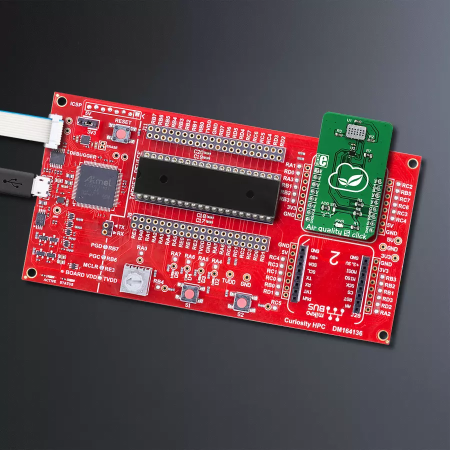
Step by step
Project assembly

Start by selecting your development board and Click board™. Begin with the Curiosity HPC as your development board.


Software Support
Library Description
This library contains API for Air Quality 5 Click driver.
Key functions:
airq5_write_data- Functions for write data in registerairq5_read_data- Functions for read data from registerairq5_set_configuration- Functions for configuration
Open Source
Code example
The complete application code and a ready-to-use project are available through the NECTO Studio Package Manager for direct installation in the NECTO Studio. The application code can also be found on the MIKROE GitHub account.
/*!
 * \file
 * \brief Airquality5 Click example
 *
 * # Description
 * This application can detect gas pollution for a number of different gases.
 *
 * The demo application is composed of two sections :
 *
 * ## Application Init
 * Initializes device and configuration chip.
 *
 * ## Application Task
 * Reads the values of CO, NH3 and NO2 sensor and logs data on USBUART every 500ms.
 *
 * \author MikroE Team
 *
 */
// ------------------------------------------------------------------- INCLUDES

#include "board.h"
#include "log.h"
#include "airquality5.h"

// ------------------------------------------------------------------ VARIABLES

static airquality5_t airquality5;
static log_t logger;

// ------------------------------------------------------ APPLICATION FUNCTIONS

void application_init ( void )
{
    log_cfg_t log_cfg;
    airquality5_cfg_t cfg;
    airquality5.data_config = 0x8583;

    /**
     * Logger initialization.
     * Default baud rate: 115200
     * Default log level: LOG_LEVEL_DEBUG
     * @note If USB_UART_RX and USB_UART_TX
     * are defined as HAL_PIN_NC, you will
     * need to define them manually for log to work.
     * See @b LOG_MAP_USB_UART macro definition for detailed explanation.
     */
    LOG_MAP_USB_UART( log_cfg );
    log_init( &logger, &log_cfg );
    log_info( &logger, "---- Application Init ----" );

    //  Click initialization.

    airquality5_cfg_setup( &cfg );
    AIRQUALITY5_MAP_MIKROBUS( cfg, MIKROBUS_1 );
    airquality5_init( &airquality5, &cfg );
}

void application_task ( void )
{
    //  Task implementation.

    uint16_t NO2_sensor_data;
    uint16_t NH3_sensor_data;
    uint16_t CO_sensor_data;

    CO_sensor_data = airq5_read_sensor_data( &airquality5, AIRQ5_DATA_CHANNEL_CO );

    NO2_sensor_data = airq5_read_sensor_data( &airquality5, AIRQ5_DATA_CHANNEL_NO2 );
    log_printf( &logger, " NO2 data: %d\r\n", NO2_sensor_data );

    NH3_sensor_data = airq5_read_sensor_data( &airquality5, AIRQ5_DATA_CHANNEL_NH3 );
    log_printf( &logger, " NH3 data: %d\r\n", NH3_sensor_data );

    CO_sensor_data = airq5_read_sensor_data( &airquality5, AIRQ5_DATA_CHANNEL_CO );
    log_printf( &logger," CO data: %d\r\n", CO_sensor_data );

    log_printf( &logger, " -------- ");
    Delay_ms ( 200 );
}

int main ( void )
{
    /* Do not remove this line or clock might not be set correctly. */
    #ifdef PREINIT_SUPPORTED
    preinit();
    #endif

    application_init( );

    for ( ; ; )
    {
        application_task( );
    }

    return 0;
}

// ------------------------------------------------------------------------ END
Additional Support
Resources
Category:Gas


