Achieve a secure and efficient way to store sensitive data using AT24CM02 and PIC32MZ2048EFH100
Store. Retrieve. Repeat.
Published Aug 23, 2023
Click board™
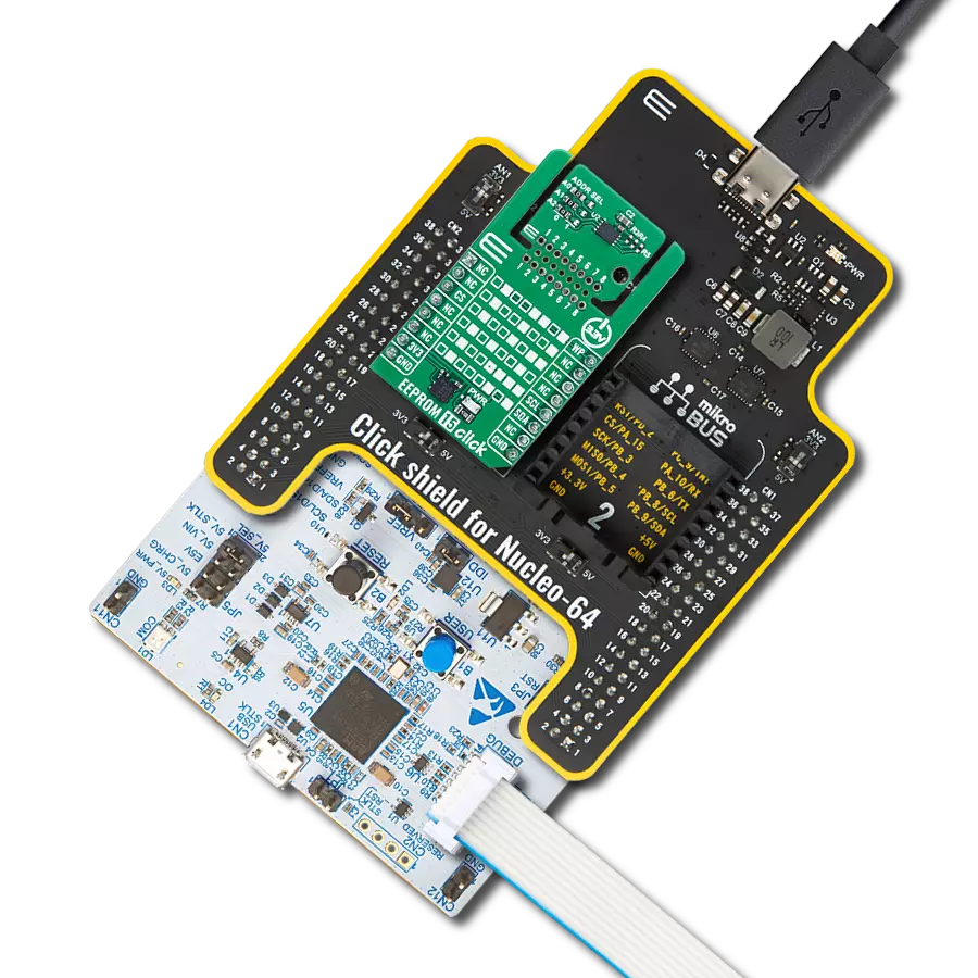
EEPROM 3 click
Dev. board
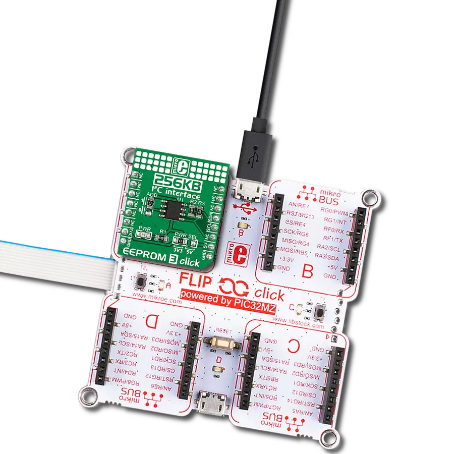
Flip&Click PIC32MZ
Compiler
NECTO Studio
MCU
PIC32MZ2048EFH100
Our solution leverages EEPROM memory for seamless integration of over-the-air updates, simplifying software deployment and enhancing the agility of your technology
A
A
Hardware Overview
How does it work?
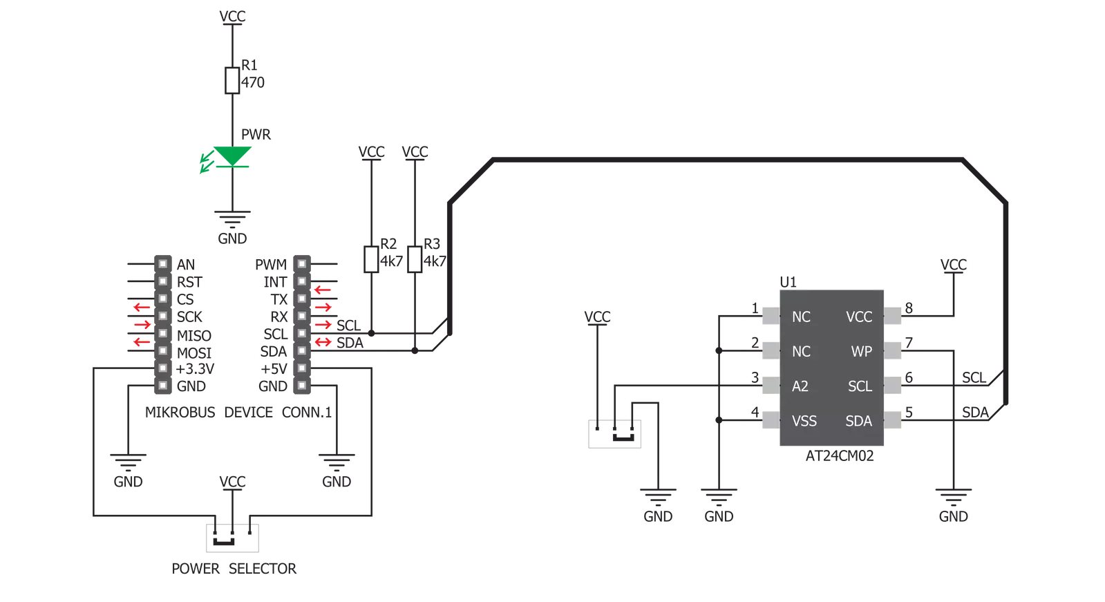
EEPROM 3 Click is based on the AT24CM02, an I2C serial EEPROM from Microchip. The EEPROM density is usually expressed in bits, so exactly 2,097,152 bits are organized in units or words of 8 bits, which gives 262,144 bytes of data memory. Furthermore, the EEPROM is organized in so-called pages. One page holds 256 bytes, and there are 1024 pages (1024 pages x 256 bytes = 262,144 bytes total). Having insight into how the memory cells are organized is important for Write and Erase operations. One of the key features of the
AT24CM02 IC is the Error Detection and Correction scheme (EDC), which allows error correction by utilizing six additional bits internally assigned to a group of four bytes. This protection scheme can correct some types of bit errors, staying transparent to the end user. The bit comparison and error correction are done internally. EEPROM 3 Click uses a standard 2-Wire I2C interface to communicate with the host MCU, supporting clock speeds of up to 1MHz. The I2C address can be selected over the ADD jumper, where 1 is set by
default. Several read modes are available, including current address read, random address read, and sequential address read. This Click board™ can operate with either 3.3V or 5V logic voltage levels selected via the PWR SEL jumper. This way, both 3.3V and 5V capable MCUs can use the communication lines properly. Also, this Click board™ comes equipped with a library containing easy-to-use functions and an example code that can be used as a reference for further development.

Features overview
Development board
Flip&Click PIC32MZ is a compact development board designed as a complete solution that brings the flexibility of add-on Click boards™ to your favorite microcontroller, making it a perfect starter kit for implementing your ideas. It comes with an onboard 32-bit PIC32MZ microcontroller, the PIC32MZ2048EFH100 from Microchip, four mikroBUS™ sockets for Click board™ connectivity, two USB connectors, LED indicators, buttons, debugger/programmer connectors, and two headers compatible with Arduino-UNO pinout. Thanks to innovative manufacturing technology,
it allows you to build gadgets with unique functionalities and features quickly. Each part of the Flip&Click PIC32MZ development kit contains the components necessary for the most efficient operation of the same board. In addition, there is the possibility of choosing the Flip&Click PIC32MZ programming method, using the chipKIT bootloader (Arduino-style development environment) or our USB HID bootloader using mikroC, mikroBasic, and mikroPascal for PIC32. This kit includes a clean and regulated power supply block through the USB Type-C (USB-C) connector. All communication
methods that mikroBUS™ itself supports are on this board, including the well-established mikroBUS™ socket, user-configurable buttons, and LED indicators. Flip&Click PIC32MZ development kit allows you to create a new application in minutes. Natively supported by Mikroe software tools, it covers many aspects of prototyping thanks to a considerable number of different Click boards™ (over a thousand boards), the number of which is growing every day.

Microcontroller Overview
MCU Card / MCU

Architecture
PIC32
MCU Memory (KB)
2048
Silicon Vendor
Microchip
Pin count
100
RAM (Bytes)
524288
Used MCU Pins
mikroBUS™ mapper
Take a closer look
Click board™ Schematic
Step by step
Project assembly

Start by selecting your development board and Click board™. Begin with the Flip&Click PIC32MZ as your development board.


Track your results in real time
Application Output
1. Application Output - In Debug mode, the 'Application Output' window enables real-time data monitoring, offering direct insight into execution results. Ensure proper data display by configuring the environment correctly using the provided tutorial.

2. UART Terminal - Use the UART Terminal to monitor data transmission via a USB to UART converter, allowing direct communication between the Click board™ and your development system. Configure the baud rate and other serial settings according to your project's requirements to ensure proper functionality. For step-by-step setup instructions, refer to the provided tutorial.

3. Plot Output - The Plot feature offers a powerful way to visualize real-time sensor data, enabling trend analysis, debugging, and comparison of multiple data points. To set it up correctly, follow the provided tutorial, which includes a step-by-step example of using the Plot feature to display Click board™ readings. To use the Plot feature in your code, use the function: plot(*insert_graph_name*, variable_name);. This is a general format, and it is up to the user to replace 'insert_graph_name' with the actual graph name and 'variable_name' with the parameter to be displayed.

Software Support
Library Description
This library contains API for EEPROM 3 Click driver.
Key functions:
eeprom3_write_byte- This function writes data to the desired registereeprom3_write_page- This function writes given number of data to the desired registereeprom3_read- This function reads data from the desired register.
Open Source
Code example
The complete application code and a ready-to-use project are available through the NECTO Studio Package Manager for direct installation in the NECTO Studio. The application code can also be found on the MIKROE GitHub account.
/*!
 * \file
 * \brief Eeprom3 Click example
 *
 * # Description
 * This application demonstrates the process of reading and writing to the EEPROM.
 *
 * The demo application is composed of two sections :
 *
 * ## Application Init
 * Initializes EEPROM 3 driver.
 *
 * ## Application Task
 * Writing data to EEPROM, reading that data and displaying it via UART
 *
 * \author MikroE Team
 *
 */
// ------------------------------------------------------------------- INCLUDES

#include "board.h"
#include "log.h"
#include "eeprom3.h"

// ------------------------------------------------------------------ VARIABLES

static eeprom3_t eeprom3;
static log_t logger;
uint8_t text[ 7 ] = { 'M','i','k','r','o','e' };
uint8_t mem_value[ 7 ] = { 0 };

// ------------------------------------------------------ APPLICATION FUNCTIONS

void application_init ( void )
{
    log_cfg_t log_cfg;
    eeprom3_cfg_t cfg;

    /**
     * Logger initialization.
     * Default baud rate: 115200
     * Default log level: LOG_LEVEL_DEBUG
     * @note If USB_UART_RX and USB_UART_TX
     * are defined as HAL_PIN_NC, you will
     * need to define them manually for log to work.
     * See @b LOG_MAP_USB_UART macro definition for detailed explanation.
     */
    LOG_MAP_USB_UART( log_cfg );
    log_init( &logger, &log_cfg );
    log_info( &logger, "---- Application Init ----" );

    //  Click initialization.
    eeprom3_cfg_setup( &cfg );
    EEPROM3_MAP_MIKROBUS( cfg, MIKROBUS_1 );
    eeprom3_init( &eeprom3, &cfg );
}

void application_task ( void )
{
    eeprom3_write_page( &eeprom3, 0x100, text, 6 );
    log_printf( &logger, "Writing Mikroe to EEPROM 3 Click\r\n" );
    Delay_ms ( 1000 );

    eeprom3_read( &eeprom3, 0x100, mem_value, 6 );
    log_printf( &logger, "Data read: %s\r\n", mem_value );
    Delay_ms ( 1000 );
}

int main ( void )
{
    /* Do not remove this line or clock might not be set correctly. */
    #ifdef PREINIT_SUPPORTED
    preinit();
    #endif

    application_init( );

    for ( ; ; )
    {
        application_task( );
    }

    return 0;
}


// ------------------------------------------------------------------------ END