Get to know your heart with BH1792GLC and PIC32MZ2048EFH100
In sync with your heartbeat

Published Jul 01, 2023
Click board™
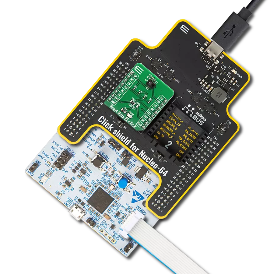
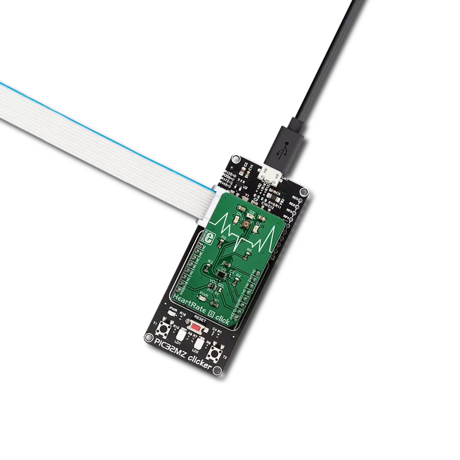
Heart Rate 8 Click
Dev. board
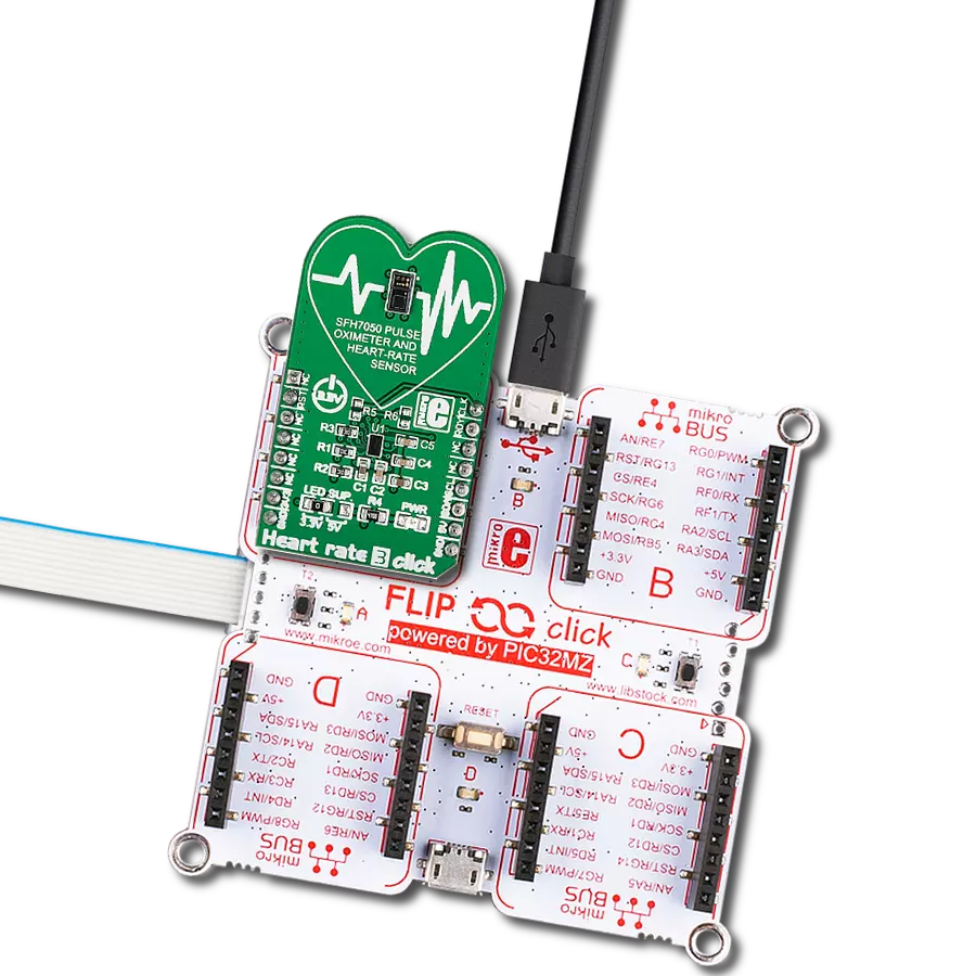
Flip&Click PIC32MZ
Compiler
NECTO Studio
MCU
PIC32MZ2048EFH100
Reach new heights with personalized heart rate monitoring
A
A
Hardware Overview
How does it work?
Heart rate 8 Click is based on the BH1792GLC, a monolithically integrated sensor for heart rate monitoring, from ROHM Semiconductor. This IC is a highly integrated optical sensor well-suited for performing PPM measurements. Due to the large integration scale of this sensor, as well as its low power consumption, it is perfectly suited to be used on a wearable IoT device. However, being a Click board™, Heart rate 8 click allows easy evaluation and rapid application and firmware development. Two green LEDs are driven by the integrated LED driving section of the BH1790GLC sensor, with the programmable Synchronized Measurement mode, with a measuring frequency between 32Hz and 1024Hz. While in this mode, two green LEDs will operate at various frequencies between 32Hz and 1024Hz, depending on the MSR bits of the measurement mode register. This allows automatic LED burst rate adjustment for achieving optimal readings. In this mode, a programmed number of measurements will be performed, and the readings will be stored on the 35 samples' deep FIFO buffer. LED current can be programmed from 0 to 63 mA, providing another control layer while using this mode. Upon receiving the MEAS_SYNC command, the measurement is performed by setting the MEAS_SYNC bit to logic 1. There are also two additional modes: Non-Synchronized, and Single Measurement mode, both allowing the IR LED to
detect an IR-emitting object, such as the hand or finger. The current through the LEDs can also be programmed from 0 to 63mA for both the IR and the green LEDs. Non-Synchronized mode offers a fixed 4 Hz LED burst operation, while the Single Measurement mode allows manual control of all the parameters. No data will be stored on the FIFO buffer in this mode. Upon receiving the MEAS_ST command, the measurement is performed by setting the MEAS_ST bit to logic 1. The reflected light burst is detected by a sensing element as a photo-diode, sampled by a low-noise 16-bit A/D converter. The photo-diodes are located behind two light filters which pass only a narrow band of green light in the range from 520nm to 560nm, with a 0.8X reduction in the center frequency. The top filter is an IRCUT filter that prevents the influence of the IR light, while the second filtering layer only passes the green light. This allows an even broader color range of LEDs to be used, reducing the overall cost of the design. However, Heart rate 8 click uses a pair of specialized green LEDs with a spectral response closely matched to the passband properties of the optical filter. This allows most of the LED energy to be used, further improving the power consumption profile. The second A/D converter does not filter light, allowing the light from the IR diode to be sensed. This is useful when a separate detection of the IR spectrum is required, for example, to detect an
approach of the finger. The IR LED driver is physically shared with the second green LED driver, but the IR LED has its dedicated pin. Two sets of four output registers contain the 16-bit measurement data in the form of two 8-bit words for the measurement when the LEDs are ON and when the LEDs are OFF. The upper and the lower 8-bit registers contain the measurement data, which can be retrieved over the standard I2C interface. The datasheet of the BH1792GLC contains the correct algorithms, which describe the measurement process in more detail. However, the Click board™ comes with the library, which contains functions that allow measurements to be performed with minimum effort. A dedicated programmable INT pin can signal an interrupt to the host MCU. The interrupt can be triggered for several events, including the data ready event (measurement completed), an event when the IR threshold is exceeded, and a so-called watermark event when the FIFO buffer is nearly full. It can also be completely disabled. The INT pin is routed to the INT pin of the mikroBUS™. A low number of external components required by the BH1792GLC sensor allows enough room on the Click board™ for the PCA9306 IC, a well-known I2C level translator, allowing the Heart rate 8 click to be interfaced with many different MCUs, both operating with 3.3V and 5V logic levels.


Features overview
Development board
Flip&Click PIC32MZ is a compact development board designed as a complete solution that brings the flexibility of add-on Click boards™ to your favorite microcontroller, making it a perfect starter kit for implementing your ideas. It comes with an onboard 32-bit PIC32MZ microcontroller, the PIC32MZ2048EFH100 from Microchip, four mikroBUS™ sockets for Click board™ connectivity, two USB connectors, LED indicators, buttons, debugger/programmer connectors, and two headers compatible with Arduino-UNO pinout. Thanks to innovative manufacturing technology,
it allows you to build gadgets with unique functionalities and features quickly. Each part of the Flip&Click PIC32MZ development kit contains the components necessary for the most efficient operation of the same board. In addition, there is the possibility of choosing the Flip&Click PIC32MZ programming method, using the chipKIT bootloader (Arduino-style development environment) or our USB HID bootloader using mikroC, mikroBasic, and mikroPascal for PIC32. This kit includes a clean and regulated power supply block through the USB Type-C (USB-C) connector. All communication
methods that mikroBUS™ itself supports are on this board, including the well-established mikroBUS™ socket, user-configurable buttons, and LED indicators. Flip&Click PIC32MZ development kit allows you to create a new application in minutes. Natively supported by Mikroe software tools, it covers many aspects of prototyping thanks to a considerable number of different Click boards™ (over a thousand boards), the number of which is growing every day.

Microcontroller Overview
MCU Card / MCU

Architecture
PIC32
MCU Memory (KB)
2048
Silicon Vendor
Microchip
Pin count
100
RAM (Bytes)
524288
Used MCU Pins
mikroBUS™ mapper
Take a closer look
Click board™ Schematic

Step by step
Project assembly

Start by selecting your development board and Click board™. Begin with the Flip&Click PIC32MZ as your development board.


Track your results in real time
Application Output
1. Application Output - In Debug mode, the 'Application Output' window enables real-time data monitoring, offering direct insight into execution results. Ensure proper data display by configuring the environment correctly using the provided tutorial.

2. UART Terminal - Use the UART Terminal to monitor data transmission via a USB to UART converter, allowing direct communication between the Click board™ and your development system. Configure the baud rate and other serial settings according to your project's requirements to ensure proper functionality. For step-by-step setup instructions, refer to the provided tutorial.

3. Plot Output - The Plot feature offers a powerful way to visualize real-time sensor data, enabling trend analysis, debugging, and comparison of multiple data points. To set it up correctly, follow the provided tutorial, which includes a step-by-step example of using the Plot feature to display Click board™ readings. To use the Plot feature in your code, use the function: plot(*insert_graph_name*, variable_name);. This is a general format, and it is up to the user to replace 'insert_graph_name' with the actual graph name and 'variable_name' with the parameter to be displayed.

Software Support
Library Description
This library contains API for Heart rate 8 Click driver.
Key functions:
heartrate8_get_data- Function gets the selected data from the determined LED Data registersheartrate8_check_int- Function checks INT pin, is interrupt occured or notheartrate8_meas_sync- Function performs the measurement synchronization
Open Source
Code example
The complete application code and a ready-to-use project are available through the NECTO Studio Package Manager for direct installation in the NECTO Studio. The application code can also be found on the MIKROE GitHub account.
/*!
 * \file
 * \brief HeartRate8 Click example
 *
 * # Description
 * This example demonstrates the use of Hearth rate 8 Click board.
 *
 * The demo application is composed of two sections :
 *
 * ## Application Init
 * Performs the device reset, after which the device configuration can be performed. The device is configured to work in Single Measurement Mode with LED pulsing.
 * The driver which is selected is driver for the GREEN LED Data.
 *
 * ## Application Task
 * Sends command to start measurement cycle, then waits until measurement cycle is finished.
 * When measurement cycle is done, gets LED ON and LED OFF Data for the selected LED driver (GREEN or IR LED) and performs data
 * plotting on serial plotter every 35ms.
 *
 *
 * \author MikroE Team
 *
 */
// ------------------------------------------------------------------- INCLUDES

#include "board.h"
#include "log.h"
#include "heartrate8.h"

// ------------------------------------------------------------------ VARIABLES

static heartrate8_t heartrate8;
static log_t logger;

static uint8_t int_check;
static uint16_t led_data_on;
static uint16_t led_data_off;
static uint32_t i;

// ------------------------------------------------------- ADDITIONAL FUNCTIONS

void plot_res( uint16_t plot_data )
{
    log_printf( &logger, "%u,%u\n", plot_data, ++i );

    if ( i == 0xFFFFFFFF )
    {
        i = 0;
    }
    Delay_ms ( 35 );
}

void log_res( )
{
    log_printf( &logger, "LED ON Data : %u      ", led_data_on );

    log_printf( &logger, "LED OFF Data : %u\n", led_data_off );

    Delay_ms ( 100 );
}

// ------------------------------------------------------ APPLICATION FUNCTIONS

void application_init ( void )
{
    log_cfg_t log_cfg;
    heartrate8_cfg_t cfg;

    /**
     * Logger initialization.
     * Default baud rate: 115200
     * Default log level: LOG_LEVEL_DEBUG
     * @note If USB_UART_RX and USB_UART_TX
     * are defined as HAL_PIN_NC, you will
     * need to define them manually for log to work.
     * See @b LOG_MAP_USB_UART macro definition for detailed explanation.
     */
    LOG_MAP_USB_UART( log_cfg );
    log_init( &logger, &log_cfg );
    log_info( &logger, "---- Application Init ----" );

    //  Click initialization.

    heartrate8_cfg_setup( &cfg );
    HEARTRATE8_MAP_MIKROBUS( cfg, MIKROBUS_1 );
    heartrate8_init( &heartrate8, &cfg );
    heartrate8_default_cfg( &heartrate8 );
    i = 0;
}

void application_task ( void )
{
    heartrate8_start_measure( &heartrate8 );

    int_check = heartrate8_check_int( &heartrate8 );
    while ( int_check != HEARTRATE8_INT_ACTIVE )
    {
        int_check = heartrate8_check_int( &heartrate8 );
    }

    heartrate8_get_data( &heartrate8, HEARTRATE8_GREEN_DATA_GET, &led_data_on, &led_data_off );
    plot_res( led_data_on );
    int_check = heartrate8_int_clear( &heartrate8 );

    Delay_ms ( 5 );
}

int main ( void )
{
    /* Do not remove this line or clock might not be set correctly. */
    #ifdef PREINIT_SUPPORTED
    preinit();
    #endif

    application_init( );

    for ( ; ; )
    {
        application_task( );
    }

    return 0;
}


// ------------------------------------------------------------------------ END
Additional Support
Resources
Category:Biometrics