Power up your audio world with ADA4254 and STM32L496AG
Hear every note in clarity

Published Jul 22, 2025
Click board™
GainAMP 3 Click
Dev. board
Discovery kit with STM32L496AG MCU
Compiler
NECTO Studio
MCU
STM32L496AG
Take control of your audio with our programmable gain instrumentation amplifier, offering precise gain adjustment for optimal sound customization
A
A
Hardware Overview
How does it work?
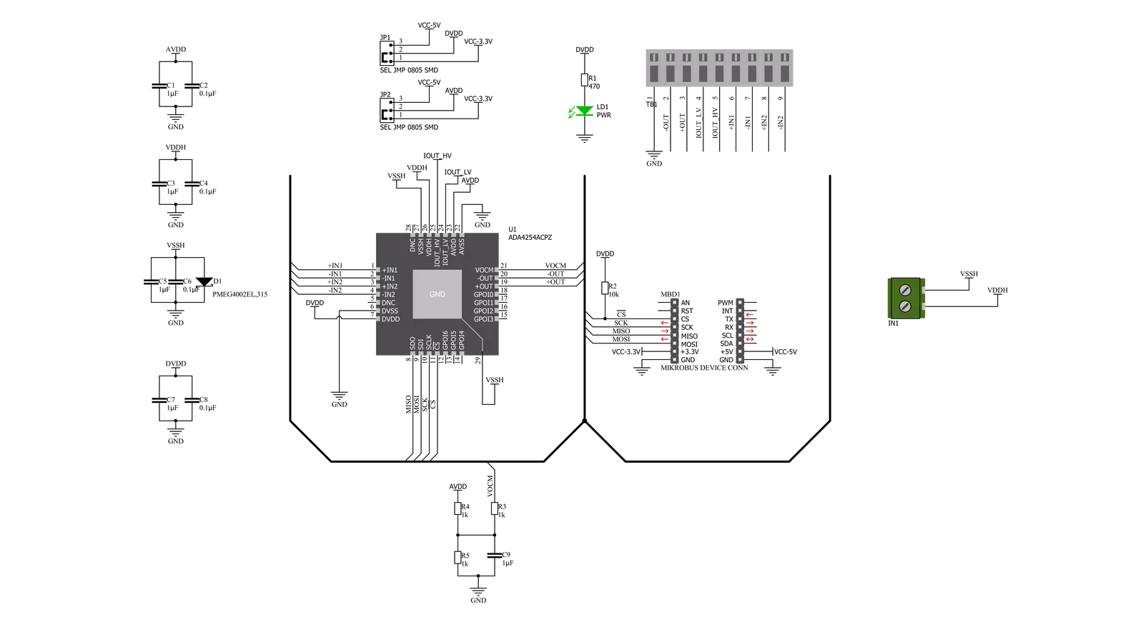
GainAMP 3 Click is based on the ADA4254, a zero drift, high voltage, programmable gain instrumentation amplifier (PGIA) designed for process control and industrial applications from Analog Devices. It accurately measures sensors, voltages, and currents with wide dynamic ranges and provides safety information about what is being measured. It features 12 binary weighted gains ranging from 1/16V/V to 128V/V and three scaling gain options of 1V/V, 1.25V/V, and 1.375V/V, resulting in 36 possible gain settings. Its zero-drift amplifier topology self-calibrates DC errors and low-frequency noise, achieving excellent DC precision over the entire specified temperature range, maximizing dynamic range, and significantly reducing calibration requirements in many applications.
The ADA4254 communicates with MCU using the standard SPI serial interface with a maximum frequency of 5MHz, supporting the most common SPI mode, SPI Mode 0. It comes with a 4-channel input multiplexer providing ±60V protection to the high impedance inputs of the amplifier and an excitation current source output available to bias sensors such as resistance temperature detectors (RTDs). In addition to these channels located on the onboard 9-pole connector, the ADA4254 also has a differential output stage and output excitation current channels. A differential output stage lets the device connect to high-precision ADCs directly. When making such a connection, it is recommended to use a low-pass filter before a connection to the ADCs to minimize noise
and aliasing. A software configurable excitation current outputs can be used to excite external circuitry, such as resistive bridges or RTD sensors, and be programmed to a value from 100μA to 1.5mA in increments of 100μA. This Click board™ can operate with either 3.3V or 5V logic voltage levels selected via the VCC SEL jumper. In addition to choosing the logic voltage level using a jumper labeled DIGI, selecting the amplifier's supply voltage using the AN jumper by positioning SMD jumpers to an appropriate position is possible. This way, both 3.3V and 5V capable MCUs can use the communication lines properly. However, the Click board™ comes equipped with a library containing easy-to-use functions and an example code that can be used, as a reference, for further development.

Features overview
Development board
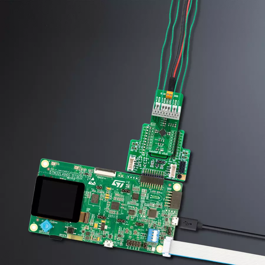
The 32L496GDISCOVERY Discovery kit serves as a comprehensive demonstration and development platform for the STM32L496AG microcontroller, featuring an Arm® Cortex®-M4 core. Designed for applications that demand a balance of high performance, advanced graphics, and ultra-low power consumption, this kit enables seamless prototyping for a wide range of embedded solutions. With its innovative energy-efficient
architecture, the STM32L496AG integrates extended RAM and the Chrom-ART Accelerator, enhancing graphics performance while maintaining low power consumption. This makes the kit particularly well-suited for applications involving audio processing, graphical user interfaces, and real-time data acquisition, where energy efficiency is a key requirement. For ease of development, the board includes an onboard ST-LINK/V2-1
debugger/programmer, providing a seamless out-of-the-box experience for loading, debugging, and testing applications without requiring additional hardware. The combination of low power features, enhanced memory capabilities, and built-in debugging tools makes the 32L496GDISCOVERY kit an ideal choice for prototyping advanced embedded systems with state-of-the-art energy efficiency.

Microcontroller Overview
MCU Card / MCU

Architecture
ARM Cortex-M4
MCU Memory (KB)
1024
Silicon Vendor
STMicroelectronics
Pin count
169
RAM (Bytes)
327680
Used MCU Pins
mikroBUS™ mapper
Take a closer look
Click board™ Schematic
Step by step
Project assembly

Start by selecting your development board and Click board™. Begin with the Discovery kit with STM32L496AG MCU as your development board.


Software Support
Library Description
This library contains API for GainAMP 3 Click driver.
Key functions:
gainamp3_write_register- This function writes a data byte to the selected register by using SPI serial interface.gainamp3_set_amplifier_gain- This function sets the amplifier gain level.gainamp3_set_input_channel- This function sets the input channel.
Open Source
Code example
The complete application code and a ready-to-use project are available through the NECTO Studio Package Manager for direct installation in the NECTO Studio. The application code can also be found on the MIKROE GitHub account.
/*!
 * @file main.c
 * @brief GainAMP3 Click example
 *
 * # Description
 * This example demonstrates the use of GainAMP 3 Click board.
 *
 * The demo application is composed of two sections :
 *
 * ## Application Init
 * Initializes the driver and performs the Click default configuration which
 * verifies the communication and sets active the input channel 1.
 *
 * ## Application Task
 * Changes the amplifier gain level every 3 seconds and displays the gain value on the USB UART.
 *
 * @note
 * VDDH should be within the range from +5V to +30V.
 * VSSH should be within the range from -5V to -30V.
 * Input channels should be within the range from GND to VCC selected by the VCC_SEL SMD jumpers.
 * Gain * Input voltage must not exceed VCC voltage.
 *
 * @author Stefan Filipovic
 *
 */

#include "board.h"
#include "log.h"
#include "gainamp3.h"

static gainamp3_t gainamp3;
static log_t logger;

void application_init ( void )
{
    log_cfg_t log_cfg;            /**< Logger config object. */
    gainamp3_cfg_t gainamp3_cfg;  /**< Click config object. */

    /**
     * Logger initialization.
     * Default baud rate: 115200
     * Default log level: LOG_LEVEL_DEBUG
     * @note If USB_UART_RX and USB_UART_TX
     * are defined as HAL_PIN_NC, you will
     * need to define them manually for log to work.
     * See @b LOG_MAP_USB_UART macro definition for detailed explanation.
     */
    LOG_MAP_USB_UART( log_cfg );
    log_init( &logger, &log_cfg );
    log_info( &logger, " Application Init " );

    // Click initialization.

    gainamp3_cfg_setup( &gainamp3_cfg );
    GAINAMP3_MAP_MIKROBUS( gainamp3_cfg, MIKROBUS_1 );
    err_t init_flag = gainamp3_init( &gainamp3, &gainamp3_cfg );
    if ( SPI_MASTER_ERROR == init_flag )
    {
        log_error( &logger, " Application Init Error. " );
        log_info( &logger, " Please, run program again... " );

        for ( ; ; );
    }

    init_flag = gainamp3_default_cfg ( &gainamp3 );
    if ( GAINAMP3_ERROR == init_flag )
    {
        log_error( &logger, " Default Config Error. " );
        log_info( &logger, " Please, run program again... " );

        for ( ; ; );
    }

    log_info( &logger, " Application Task " );
}

void application_task ( void )
{
    for ( uint8_t cnt = GAINAMP3_GAIN_1_OVER_16; cnt <= GAINAMP3_GAIN_128; cnt++ )
    {
        gainamp3_set_amplifier_gain ( &gainamp3, cnt );
        log_printf( &logger, " Amplifier gain set to " );
        float gain = ( 1 << cnt ) / 16.0;

        if ( gain < 1.0 )
        {
            log_printf( &logger, "1/%u\r\n", ( uint16_t ) ( 1.0 / gain ) );
        }
        else
        {
            log_printf( &logger, "%u\r\n", ( uint16_t ) gain );
        }
        Delay_ms ( 1000 );
        Delay_ms ( 1000 );
        Delay_ms ( 1000 );
    }
}

int main ( void )
{
    /* Do not remove this line or clock might not be set correctly. */
    #ifdef PREINIT_SUPPORTED
    preinit();
    #endif

    application_init( );

    for ( ; ; )
    {
        application_task( );
    }

    return 0;
}

// ------------------------------------------------------------------------ END
Additional Support
Resources
Category:Amplifier


