Enrich every note and deliver an unparalleled auditory journey using MAX9723 and PIC32MZ2048EFM100
Turn up the quality, not just the volume!

Published Nov 13, 2023
Click board™
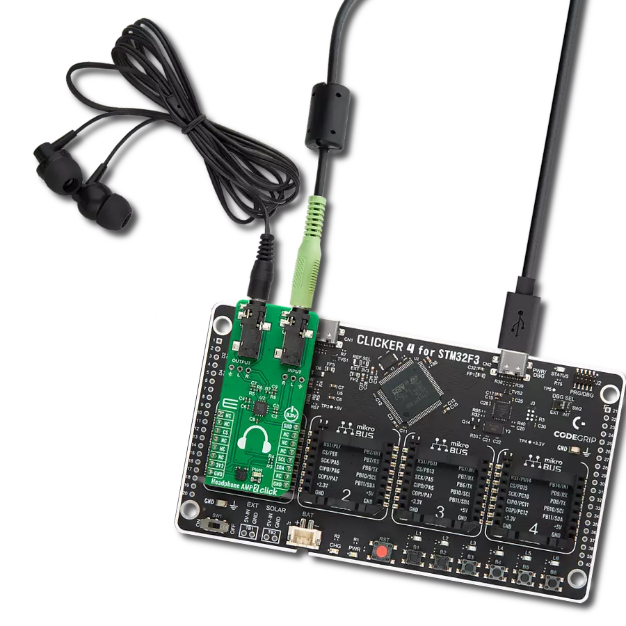
Headphone AMP 2 Click
Dev. board
Curiosity PIC32 MZ EF
Compiler
NECTO Studio
MCU
PIC32MZ2048EFM100
Our headphone amplifier is the ultimate companion for those who demand exceptional audio quality.
A
A
Hardware Overview
How does it work?
Headphone AMP 2 Click is based on the MAX9723, a stereo DirectDrive headphone amplifier with BassMax, volume control, and I2C from Analog Devices. The headphone amplifier uses a DirectDrive architecture that produces a ground-referenced output from a single supply, thus eliminating the need for large DC-blocking capacitors. Its outputs are biased at 0V, making the amplifier outputs not have a DC component, improving a low-frequency response. The DirectDrive architecture uses a charge pump to create an internal negative supply voltage, which makes the dynamic range from a single supply almost double. Software-enabled bass boost (BassMax) boosts the bass response of the
amplifier, improving audio reproduction when using inexpensive headphones. This, in particular, comes in handy when reproducing low frequencies, where the limitations of the small physical size of the diaphragm are compensated by increasing the amplifier gain. The maximum amplifier gain on this chip is +6dB. The volume control adjusts the gain of the output amplifiers according to your needs over the software. The amplifier can enter the low-power shutdown mode, where the host MCU controls the shutdown mode. Headphone AMP 2 Click uses a standard 2-Wire I2C interface to communicate with the host MCU, supporting clock rates of up to 400kHz. The shutdown control is available on the SHD pin of
the mikroBUS™ socket. In addition to the 3.5mm input and output audio jacks, there are corresponding two channels input and output headers in case of the need to connect inputs or outputs incompatible with jack connectors (wire types). This Click board™ can be operated only with a 3.3V logic voltage level. The board must perform appropriate logic voltage level conversion before using MCUs with different logic levels. Also, this Click board™ comes equipped with a library containing easy-to-use functions and an example code that can be used as a reference for further development.

Features overview
Development board
Curiosity PIC32 MZ EF development board is a fully integrated 32-bit development platform featuring the high-performance PIC32MZ EF Series (PIC32MZ2048EFM) that has a 2MB Flash, 512KB RAM, integrated FPU, Crypto accelerator, and excellent connectivity options. It includes an integrated programmer and debugger, requiring no additional hardware. Users can expand
functionality through MIKROE mikroBUS™ Click™ adapter boards, add Ethernet connectivity with the Microchip PHY daughter board, add WiFi connectivity capability using the Microchip expansions boards, and add audio input and output capability with Microchip audio daughter boards. These boards are fully integrated into PIC32’s powerful software framework, MPLAB Harmony,
which provides a flexible and modular interface to application development a rich set of inter-operable software stacks (TCP-IP, USB), and easy-to-use features. The Curiosity PIC32 MZ EF development board offers expansion capabilities making it an excellent choice for a rapid prototyping board in Connectivity, IOT, and general-purpose applications.

Microcontroller Overview
MCU Card / MCU

Architecture
PIC32
MCU Memory (KB)
2048
Silicon Vendor
Microchip
Pin count
100
RAM (Bytes)
524288
You complete me!
Accessories
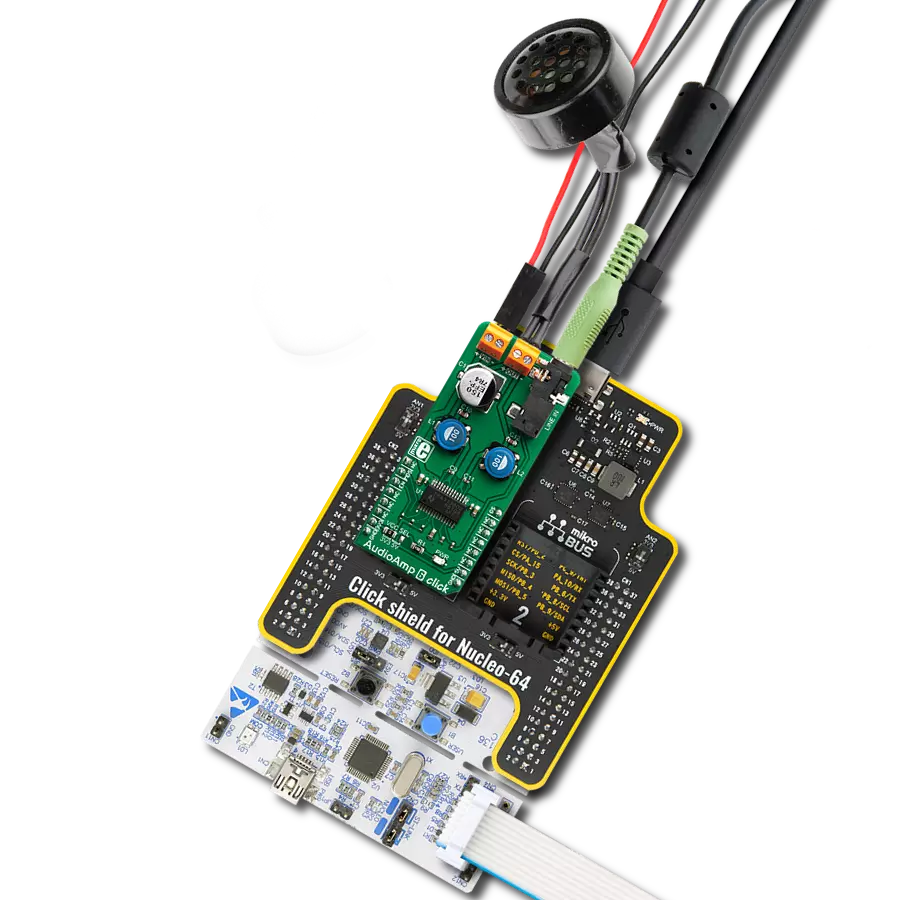
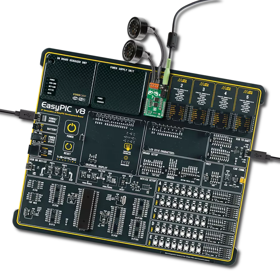
These standard small stereo earphones offer a high-quality listening experience with their top-notch stereo cable and connector. Designed for universal compatibility, they effortlessly connect to all MIKROE mikromedia and multimedia boards, making them an ideal choice for your electronic projects. With a rated power of 100mW, the earphones provide crisp audio across a broad frequency range from 20Hz to 20kHz. They boast a sensitivity of 100 ± 5dB and an impedance of 32Ω ± 15%, ensuring optimal sound quality. The Φ15mm speaker delivers clear and immersive audio. Cost-effective and versatile, these earphones are perfect for testing your prototype devices, offering an affordable and reliable audio solution to complement your projects.

Used MCU Pins
mikroBUS™ mapper
Take a closer look
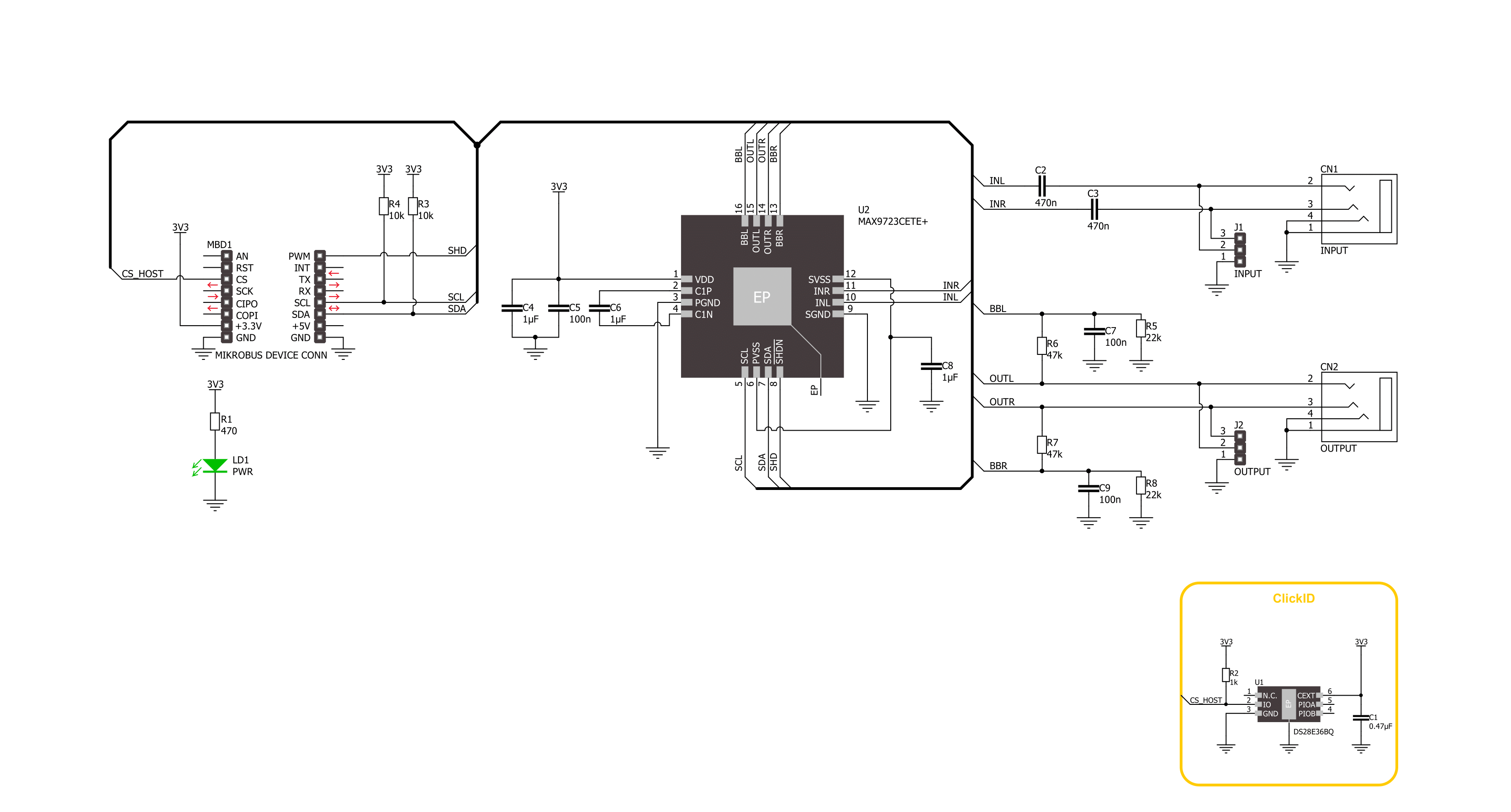
Click board™ Schematic
Step by step
Project assembly

Start by selecting your development board and Click board™. Begin with the Curiosity PIC32 MZ EF as your development board.


Track your results in real time
Application Output
1. Application Output - In Debug mode, the 'Application Output' window enables real-time data monitoring, offering direct insight into execution results. Ensure proper data display by configuring the environment correctly using the provided tutorial.

2. UART Terminal - Use the UART Terminal to monitor data transmission via a USB to UART converter, allowing direct communication between the Click board™ and your development system. Configure the baud rate and other serial settings according to your project's requirements to ensure proper functionality. For step-by-step setup instructions, refer to the provided tutorial.

3. Plot Output - The Plot feature offers a powerful way to visualize real-time sensor data, enabling trend analysis, debugging, and comparison of multiple data points. To set it up correctly, follow the provided tutorial, which includes a step-by-step example of using the Plot feature to display Click board™ readings. To use the Plot feature in your code, use the function: plot(*insert_graph_name*, variable_name);. This is a general format, and it is up to the user to replace 'insert_graph_name' with the actual graph name and 'variable_name' with the parameter to be displayed.

Software Support
Library Description
This library contains API for Headphone AMP 2 Click driver.
Key functions:
headphoneamp2_set_command- Headphone AMP 2 set the command function.headphoneamp2_enable- Headphone AMP 2 enable the device function.headphoneamp2_disable- Headphone AMP 2 disable the device function.
Open Source
Code example
The complete application code and a ready-to-use project are available through the NECTO Studio Package Manager for direct installation in the NECTO Studio. The application code can also be found on the MIKROE GitHub account.
/*!
 * @file main.c
 * @brief Headphone AMP 2 Click example
 *
 * # Description
 * This example demonstrates the use of the Headphone AMP 2 Click board™,
 * the headphone amplifier with BassMax and volume control.
 *
 * The demo application is composed of two sections :
 *
 * ## Application Init
 * The initialization of I2C module and log UART.
 * After driver initialization, the app sets the default configuration.
 *
 * ## Application Task
 * This example demonstrates the use of the Headphone AMP 2 Click board™.
 * The application wakes up the device, enables BassMax and Maximum Gain modes,
 * and switches the sound volume from level 1 to the max level.
 * Results are being sent to the UART Terminal, where you can track their changes.
 *
 * @author Nenad Filipovic
 *
 */

#include "board.h"
#include "log.h"
#include "headphoneamp2.h"

static headphoneamp2_t headphoneamp2;
static log_t logger;

void application_init ( void )
{
    log_cfg_t log_cfg;  /**< Logger config object. */
    headphoneamp2_cfg_t headphoneamp2_cfg;  /**< Click config object. */

    /**
     * Logger initialization.
     * Default baud rate: 115200
     * Default log level: LOG_LEVEL_DEBUG
     * @note If USB_UART_RX and USB_UART_TX
     * are defined as HAL_PIN_NC, you will
     * need to define them manually for log to work.
     * See @b LOG_MAP_USB_UART macro definition for detailed explanation.
     */
    LOG_MAP_USB_UART( log_cfg );
    log_init( &logger, &log_cfg );
    log_info( &logger, " Application Init " );

    // Click initialization.
    headphoneamp2_cfg_setup( &headphoneamp2_cfg );
    HEADPHONEAMP2_MAP_MIKROBUS( headphoneamp2_cfg, MIKROBUS_1 );
    if ( I2C_MASTER_ERROR == headphoneamp2_init( &headphoneamp2, &headphoneamp2_cfg ) )
    {
        log_error( &logger, " Communication init." );
        for ( ; ; );
    }

    if ( HEADPHONEAMP2_ERROR == headphoneamp2_default_cfg ( &headphoneamp2 ) )
    {
        log_error( &logger, " Default configuration." );
        for ( ; ; );
    }

    log_info( &logger, " Application Task " );
    log_printf( &logger, "-------------------------\r\n" );
    Delay_ms ( 100 );
}

void application_task ( void )
{
    static headphoneamp2_cmd_t cmd_ctrl;
    cmd_ctrl.wakes_up = HEADPHONEAMP2_CMD_ENABLE;
    cmd_ctrl.bass_max = HEADPHONEAMP2_CMD_ENABLE;
    cmd_ctrl.gain_max = HEADPHONEAMP2_CMD_ENABLE;
    cmd_ctrl.volume   = HEADPHONEAMP2_VOL_MUTE;

    log_printf( &logger, " Volume : " );
    for ( uint8_t volume = HEADPHONEAMP2_VOL_LVL_1; volume <= HEADPHONEAMP2_VOL_LVL_MAX; volume++ )
    {
        cmd_ctrl.volume = volume;
        if ( HEADPHONEAMP2_OK == headphoneamp2_set_command( &headphoneamp2, cmd_ctrl ) )
        {
            log_printf( &logger, "|" );
        }
        Delay_ms ( 1000 );
    }
    log_printf( &logger, "\r\n-------------------------\r\n" );
}

int main ( void )
{
    /* Do not remove this line or clock might not be set correctly. */
    #ifdef PREINIT_SUPPORTED
    preinit();
    #endif

    application_init( );

    for ( ; ; )
    {
        application_task( );
    }

    return 0;
}

// ------------------------------------------------------------------------ END