Simplify your connections and unlock limitless creative potential with PIC32MZ2048EFH100
mikroBUS™ signals at your fingertips

Published Nov 09, 2023
Click board™
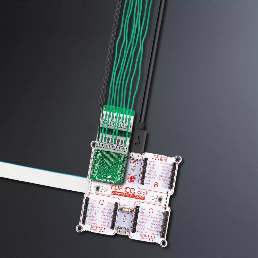
Terminal 2 Click
Dev. board
Flip&Click PIC32MZ
Compiler
NECTO Studio
MCU
PIC32MZ2048EFH100
Get easy access to mikroBUS™ signals, allowing you to tinker and experiment with your projects effortlessly.
A
A
Hardware Overview
How does it work?
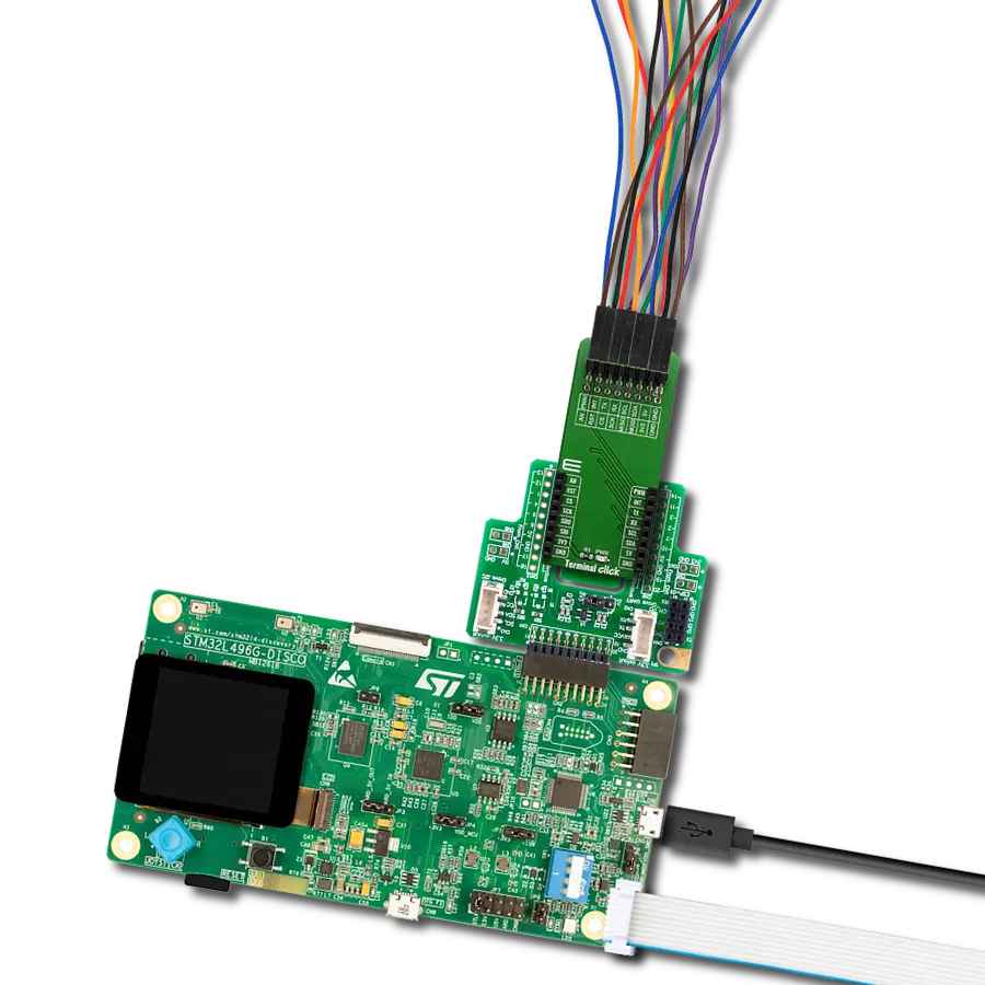
Terminal 2 Click is an adapter Click board™ used as a mikroBUS™ socket expansion board. This Click board™ provides an easy and elegant solution for adding the external connection capability to the Click board™ and can be connected to the mikroBUS™ socket like any other Click board™. On the central area of the Terminal 2 Click, two 9-position 2.54mm pitch terminal blocks are placed. Each of the terminal pins corresponds to a pin on the mikroBUS™ socket. Thanks to these terminals, the connection
with the Click board™ remains firm and stable, retaining a perfect connection quality at all times. Lines of the mikroBUS™ socket to which Terminal 2 Click is attached are shared through the onboard connectors, which mirror the connected mikroBUS™ socket pins. Therefore, care should be taken when working with the Terminal 2 Click and connecting an external device to it because the same pins on the mikroBUS™ are shared, either for the communication (SPI, UART, I2C) or for some other purpose (RST, INT, or other pins used as
GPIO). This Click board™ can operate with both 3.3V and 5V logic voltage levels. This way, it is allowed for both 3.3V and 5V capable MCUs to use the communication lines properly. A green LED visually detects the presence of an active power supply labeled as PWR. Also, this Click board™ comes equipped with a library containing easy-to-use functions and an example code that can be used as a reference for further development.

Features overview
Development board
Flip&Click PIC32MZ is a compact development board designed as a complete solution that brings the flexibility of add-on Click boards™ to your favorite microcontroller, making it a perfect starter kit for implementing your ideas. It comes with an onboard 32-bit PIC32MZ microcontroller, the PIC32MZ2048EFH100 from Microchip, four mikroBUS™ sockets for Click board™ connectivity, two USB connectors, LED indicators, buttons, debugger/programmer connectors, and two headers compatible with Arduino-UNO pinout. Thanks to innovative manufacturing technology,
it allows you to build gadgets with unique functionalities and features quickly. Each part of the Flip&Click PIC32MZ development kit contains the components necessary for the most efficient operation of the same board. In addition, there is the possibility of choosing the Flip&Click PIC32MZ programming method, using the chipKIT bootloader (Arduino-style development environment) or our USB HID bootloader using mikroC, mikroBasic, and mikroPascal for PIC32. This kit includes a clean and regulated power supply block through the USB Type-C (USB-C) connector. All communication
methods that mikroBUS™ itself supports are on this board, including the well-established mikroBUS™ socket, user-configurable buttons, and LED indicators. Flip&Click PIC32MZ development kit allows you to create a new application in minutes. Natively supported by Mikroe software tools, it covers many aspects of prototyping thanks to a considerable number of different Click boards™ (over a thousand boards), the number of which is growing every day.

Microcontroller Overview
MCU Card / MCU

Architecture
PIC32
MCU Memory (KB)
2048
Silicon Vendor
Microchip
Pin count
100
RAM (Bytes)
524288
Used MCU Pins
mikroBUS™ mapper
Take a closer look
Click board™ Schematic

Step by step
Project assembly

Start by selecting your development board and Click board™. Begin with the Flip&Click PIC32MZ as your development board.


Software Support
Library Description
This library contains API for Terminal 2 Click driver.
Key functions:
terminal2_set_all_pins_high- This function sets all terminal pins to high logic level.terminal2_set_all_pins_low- This function sets all terminal pins to low logic level.terminal2_toggle_pin- This function toggles the specified pin logic level.
Open Source
Code example
The complete application code and a ready-to-use project are available through the NECTO Studio Package Manager for direct installation in the NECTO Studio. The application code can also be found on the MIKROE GitHub account.
/*!
 * @file main.c
 * @brief Terminal 2 Click Example.
 *
 * # Description
 * This example demonstates the use of Terminal 2 Click board by toggling all its pins.
 *
 * The demo application is composed of two sections :
 *
 * ## Application Init
 * Initializes the driver and logger and sets all pins to low logic state.
 *
 * ## Application Task
 * Toggles all pins from mikroBUS one by one in the span of 1 second between each pin toggle.
 *
 * @author Stefan Filipovic
 *
 */

#include "board.h"
#include "log.h"
#include "terminal2.h"

static terminal2_t terminal2;   /**< Terminal 2 Click driver object. */
static log_t logger;    /**< Logger object. */

void application_init ( void )
{
    log_cfg_t log_cfg;  /**< Logger config object. */
    terminal2_cfg_t terminal2_cfg;  /**< Click config object. */

    /**
     * Logger initialization.
     * Default baud rate: 115200
     * Default log level: LOG_LEVEL_DEBUG
     * @note If USB_UART_RX and USB_UART_TX
     * are defined as HAL_PIN_NC, you will
     * need to define them manually for log to work.
     * See @b LOG_MAP_USB_UART macro definition for detailed explanation.
     */
    LOG_MAP_USB_UART( log_cfg );
    log_init( &logger, &log_cfg );
    log_info( &logger, " Application Init " );

    // Click initialization.
    terminal2_cfg_setup( &terminal2_cfg );
    TERMINAL2_MAP_MIKROBUS( terminal2_cfg, MIKROBUS_1 );
    if ( DIGITAL_OUT_UNSUPPORTED_PIN == terminal2_init( &terminal2, &terminal2_cfg ) )
    {
        log_error( &logger, " Communication init." );
        for ( ; ; );
    }
    terminal2_set_all_pins_low ( &terminal2 );

    log_info( &logger, " Application Task " );
}

void application_task ( void )
{
    /**< Array of pins object addresses. */
    static digital_out_t *pin_addr[ 12 ] =
    {
        &terminal2.mosi,    // 0 MOSI
        &terminal2.miso,    // 1 MISO
        &terminal2.sck,     // 2 SCK
        &terminal2.cs,      // 3 CS
        &terminal2.rst,     // 4 RST
        &terminal2.an,      // 5 AN
        &terminal2.pwm,     // 6 PWM
        &terminal2.int_pin, // 7 INT
        &terminal2.tx_pin,  // 8 TX
        &terminal2.rx_pin,  // 9 RX
        &terminal2.scl,     // 10 SCL
        &terminal2.sda      // 11 SDA
    };
    static uint8_t pin_num = 0;
    log_printf( &logger, " Toggling pin: %u\r\n", ( uint16_t ) pin_num );
    terminal2_toggle_pin ( pin_addr[ pin_num ] );
    Delay_ms ( 1000 );
    terminal2_toggle_pin ( pin_addr[ pin_num ] );

    pin_num++;
    if ( 12 == pin_num )
    {
        pin_num = 0;
    }
}

int main ( void )
{
    /* Do not remove this line or clock might not be set correctly. */
    #ifdef PREINIT_SUPPORTED
    preinit();
    #endif

    application_init( );

    for ( ; ; )
    {
        application_task( );
    }

    return 0;
}

// ------------------------------------------------------------------------ END
Additional Support
Resources
Category:Adapter