Manage various sensors and actuators with our I2C adapter and PIC32MZ2048EFH100
One Click to rule them all: Uniting devices on a single bus
Published Nov 11, 2023
Click board™
8-pin I2C Click
Dev. board
Flip&Click PIC32MZ
Compiler
NECTO Studio
MCU
PIC32MZ2048EFH100
This innovative product unlocks new possibilities in I2C connectivity, inspiring users to explore and unleash the full potential of 8-pin connections, fostering innovation and creativity in electronics projects.
A
A
Hardware Overview
How does it work?
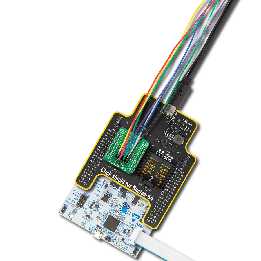
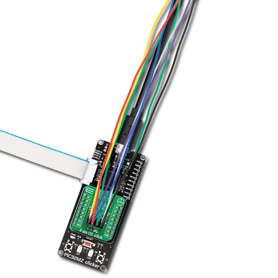
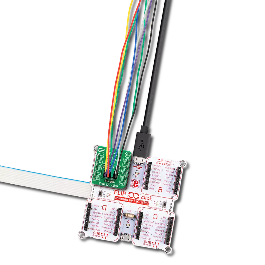
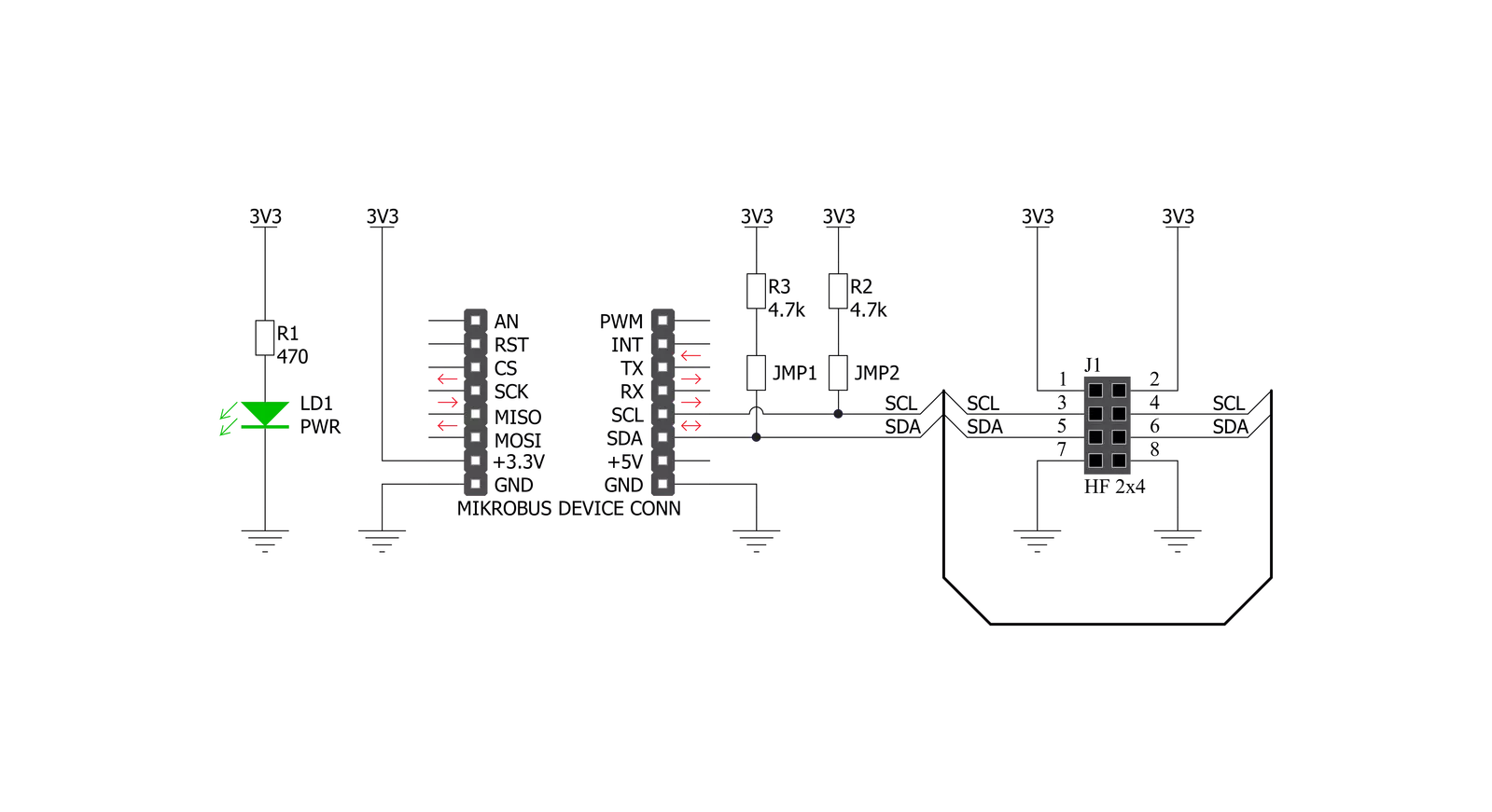
8-pin I2C Click is an adapter Click board™ that simplifies the connection of add-on boards to the mikroBUS™ socket. This Click board™ represents a small-size PCB that can be connected to the mikroBUS™ socket like any other Click board™, with a 2x4 female header placed on itself. Each header pin corresponds to a pin on the mikroBUS™ socket, such as I2C lines (SCL, SDA) with two jumpers for I2C lines pull-up function selection, 3V3 power supply, and ground. This Click board™ allows easy pin access and manipulation while always retaining a perfect connection
quality. Being compatible with Apple's MFI is the most important feature of the 8-pin I2C Click board™, which ensures its proper operation with additional Apple accessories. The name is a shortened version of the long-form Made for iPod, the original program that ultimately became MFI which refers to peripherals that work with Apple's iPod, iPad, and iPhone. 8-pin I2C Click communicates with MCU using the standard I2C 2-Wire interface. Lines of the mikroBUS™ to which this Click board™ is attached are shared through the top 8-pin female header, which mirrors
the pins of the connected mikroBUS™ socket. The 8-pin I2C Click also shares the 3V3 power rails, making it compatible with other power-compatible Click board™ and development systems. This Click board™ can only be operated with a 3.3V logic voltage level. The board must perform appropriate logic voltage level conversion before using MCUs with different logic levels. However, the Click board™ comes equipped with a library containing functions and an example code that can be used as a reference for further development.

Features overview
Development board
Flip&Click PIC32MZ is a compact development board designed as a complete solution that brings the flexibility of add-on Click boards™ to your favorite microcontroller, making it a perfect starter kit for implementing your ideas. It comes with an onboard 32-bit PIC32MZ microcontroller, the PIC32MZ2048EFH100 from Microchip, four mikroBUS™ sockets for Click board™ connectivity, two USB connectors, LED indicators, buttons, debugger/programmer connectors, and two headers compatible with Arduino-UNO pinout. Thanks to innovative manufacturing technology,
it allows you to build gadgets with unique functionalities and features quickly. Each part of the Flip&Click PIC32MZ development kit contains the components necessary for the most efficient operation of the same board. In addition, there is the possibility of choosing the Flip&Click PIC32MZ programming method, using the chipKIT bootloader (Arduino-style development environment) or our USB HID bootloader using mikroC, mikroBasic, and mikroPascal for PIC32. This kit includes a clean and regulated power supply block through the USB Type-C (USB-C) connector. All communication
methods that mikroBUS™ itself supports are on this board, including the well-established mikroBUS™ socket, user-configurable buttons, and LED indicators. Flip&Click PIC32MZ development kit allows you to create a new application in minutes. Natively supported by Mikroe software tools, it covers many aspects of prototyping thanks to a considerable number of different Click boards™ (over a thousand boards), the number of which is growing every day.

Microcontroller Overview
MCU Card / MCU

Architecture
PIC32
MCU Memory (KB)
2048
Silicon Vendor
Microchip
Pin count
100
RAM (Bytes)
524288
Used MCU Pins
mikroBUS™ mapper
Take a closer look
Click board™ Schematic
Step by step
Project assembly

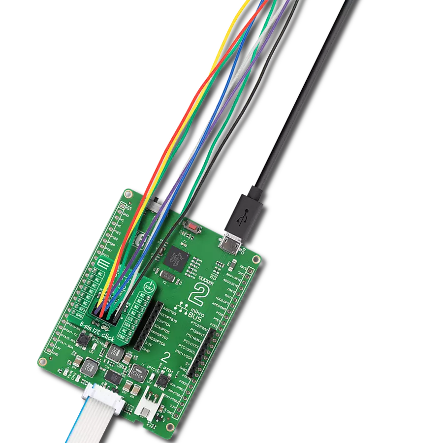
Start by selecting your development board and Click board™. Begin with the Flip&Click PIC32MZ as your development board.


Software Support
Library Description
This library contains API for 8-pin I2C Click driver.
Key functions:
c8pini2c_generic_write- Generic write function.c8pini2c_generic_read- Generic read function.
Open Source
Code example
The complete application code and a ready-to-use project are available through the NECTO Studio Package Manager for direct installation in the NECTO Studio. The application code can also be found on the MIKROE GitHub account.
/*!
 * \file
 * \brief 8pinI2c Click example
 *
 * # Description
 * This demo example reads temperature detected by Surface temp Click board.
 *
 * The demo application is composed of two sections :
 *
 * ## Application Init
 * Initializes the driver and configures a Surface temp Click board.
 *
 * ## Application Task
 * Reads the temperature detected by Surface temp Click board and
 * logs it on the USB UART each second.
 *
 * @note
 * In order to run this example successfully, a Surface temp Click board needs to be
 * connected properly to an 8-pin I2C Click board.
 *
 * \author MikroE Team
 *
 */
// ------------------------------------------------------------------- INCLUDES

#include "board.h"
#include "log.h"
#include "c8pini2c.h"

// ------------------------------------------------------------------ VARIABLES

static c8pini2c_t c8pini2c;
static log_t logger;

// Surface temp Click - example
#define SURFACE_TEMP_DEVICE_SLAVE_ADDRESS 0x48
#define SURFACE_TEMP_REG_SOFT_RESET       0x2F
#define SURFACE_TEMP_REG_ID               0x0B
#define SURFACE_TEMP_REG_CONFIG           0x03
#define SURFACE_TEMP_REG_TEMP_MSB         0x00

// ------------------------------------------------------- ADDITIONAL FUNCTIONS

void surfacetemp_soft_reset (  )
{
    uint8_t tx_data;

    tx_data = SURFACE_TEMP_REG_SOFT_RESET;

    c8pini2c_generic_write ( &c8pini2c, SURFACE_TEMP_DEVICE_SLAVE_ADDRESS,
                                        0, &tx_data, 1 );
}

uint8_t surfacetemp_setup (  )
{
    uint8_t tmp;

    surfacetemp_soft_reset( );
    Delay_100ms( );
    c8pini2c_generic_read( &c8pini2c, SURFACE_TEMP_DEVICE_SLAVE_ADDRESS,
                                      SURFACE_TEMP_REG_ID, &tmp, 1 );

    if ( tmp != 0xCB )
    {
        return 1;
    }
    tmp = 0x93;
    c8pini2c_generic_write( &c8pini2c, SURFACE_TEMP_DEVICE_SLAVE_ADDRESS,
                                       SURFACE_TEMP_REG_CONFIG, &tmp, 1 );

    return 0;
}

float surfacetemp_get_temperature (  )
{
    uint8_t rx_buff[ 2 ];
    int16_t temp;
    float temperature;

    c8pini2c_generic_read( &c8pini2c, SURFACE_TEMP_DEVICE_SLAVE_ADDRESS,
                                      SURFACE_TEMP_REG_TEMP_MSB, &rx_buff[ 0 ], 2 );

    temp = rx_buff[ 0 ];
    temp <<= 8;
    temp |= rx_buff[ 1 ];
    temp &= 0xFFF8;

    temperature = (float)(temp);
    temperature *= 0.0078;

    return temperature;
}

// ------------------------------------------------------ APPLICATION FUNCTIONS

void application_init ( void )
{
    log_cfg_t log_cfg;
    c8pini2c_cfg_t cfg;

    uint8_t status;

    /**
     * Logger initialization.
     * Default baud rate: 115200
     * Default log level: LOG_LEVEL_DEBUG
     * @note If USB_UART_RX and USB_UART_TX
     * are defined as HAL_PIN_NC, you will
     * need to define them manually for log to work.
     * See @b LOG_MAP_USB_UART macro definition for detailed explanation.
     */
    LOG_MAP_USB_UART( log_cfg );
    log_init( &logger, &log_cfg );
    log_info( &logger, "---- Application Init ----" );

    //  Click initialization.

    c8pini2c_cfg_setup( &cfg );
    C8PINI2C_MAP_MIKROBUS( cfg, MIKROBUS_1 );
    c8pini2c_init( &c8pini2c, &cfg );

    status = surfacetemp_setup( );
    if ( status == 0 )
    {
        log_printf( &logger, "--- INIT DONE --- \r\n" );
    }
    else
    {
        log_printf( &logger, "--- INIT ERROR --- \r\n" );
        for( ; ; );
    }
}

void application_task ( void )
{
    float temperature;

    temperature = surfacetemp_get_temperature( );
    log_printf( &logger, "> Temperature : %.2f Celsius\r\n", temperature );
    Delay_ms ( 1000 );
}

int main ( void )
{
    /* Do not remove this line or clock might not be set correctly. */
    #ifdef PREINIT_SUPPORTED
    preinit();
    #endif

    application_init( );

    for ( ; ; )
    {
        application_task( );
    }

    return 0;
}

// ------------------------------------------------------------------------ END
Additional Support
Resources
Category:Adapter