Step into the future of motor control with NCV70517 and PIC32MZ2048EFH100
Revolutionize automation with our all-in-one driver!

Published Oct 28, 2023
Click board™
Stepper 16 Click
Dev. board
Flip&Click PIC32MZ
Compiler
NECTO Studio
MCU
PIC32MZ2048EFH100
Our all-in-one motor-driver solution is set to revolutionize the automation industry, simplifying bipolar stepper motor control like never before
A
A
Hardware Overview
How does it work?
Stepper 16 Click is based on the NCV70517, an integrated motor-driver solution for bipolar stepper motors with integrated current sense and current regulation from ON Semiconductor. Two H−bridges are integrated to drive a bipolar stepper motor with a PWM current control loop with on-chip current sensing implemented for each H−bridge. It provides complete output protection, overcurrent protection, thermal warning and shutdown, and a proprietary PWM algorithm for reliable current control, allowing automatic selection of fast and slow decay. The NCV70517 communicates with MCU using the standard SPI serial interface with a maximum frequency 10MHz. One of five possible stepping modes is selectable through bits of the SPI registers. After Power−On
or hard reset, the coil−current translator, which translates consecutive steps into corresponding currents in both motor coils for a given step mode, is set to the default to 1/16 micro−stepping at position ‘8’. Besides the micro−step modes, a full-step mode is implemented, which activates only one coil. The direction of rotation is selected by input pin DIR routed to the RST pin of the mikroBUS™ socket and its polarity bit DIRP, which allows changing the direction of rotation through only SPI commands instead of the dedicated input pin. Besides, it also takes the next micro−step depending on the clock signal on the NXT input pin routed to the PWM pin of the mikroBUS™ socket and provides an error message on the ERR pin routed to the INT pin of the mikroBUS™ socket
if an electrical error, an undervoltage, or an elevated junction temperature is detected. This Click board™ supports an external power supply for the motor, which can be connected to the input terminal labeled as VEXT and should be within the range of 6V to 29V, while the stepper motor coils can be connected to the terminals labeled as XP, XN, YP, and YN. This Click board™ can be operated only with a 3.3V logic voltage level. The board must perform appropriate logic voltage level conversion before using MCUs with different logic levels. Also, it comes equipped with a library containing functions and an example code that can be used as a reference for further development.

Features overview
Development board
Flip&Click PIC32MZ is a compact development board designed as a complete solution that brings the flexibility of add-on Click boards™ to your favorite microcontroller, making it a perfect starter kit for implementing your ideas. It comes with an onboard 32-bit PIC32MZ microcontroller, the PIC32MZ2048EFH100 from Microchip, four mikroBUS™ sockets for Click board™ connectivity, two USB connectors, LED indicators, buttons, debugger/programmer connectors, and two headers compatible with Arduino-UNO pinout. Thanks to innovative manufacturing technology,
it allows you to build gadgets with unique functionalities and features quickly. Each part of the Flip&Click PIC32MZ development kit contains the components necessary for the most efficient operation of the same board. In addition, there is the possibility of choosing the Flip&Click PIC32MZ programming method, using the chipKIT bootloader (Arduino-style development environment) or our USB HID bootloader using mikroC, mikroBasic, and mikroPascal for PIC32. This kit includes a clean and regulated power supply block through the USB Type-C (USB-C) connector. All communication
methods that mikroBUS™ itself supports are on this board, including the well-established mikroBUS™ socket, user-configurable buttons, and LED indicators. Flip&Click PIC32MZ development kit allows you to create a new application in minutes. Natively supported by Mikroe software tools, it covers many aspects of prototyping thanks to a considerable number of different Click boards™ (over a thousand boards), the number of which is growing every day.

Microcontroller Overview
MCU Card / MCU

Architecture
PIC32
MCU Memory (KB)
2048
Silicon Vendor
Microchip
Pin count
100
RAM (Bytes)
524288
You complete me!
Accessories
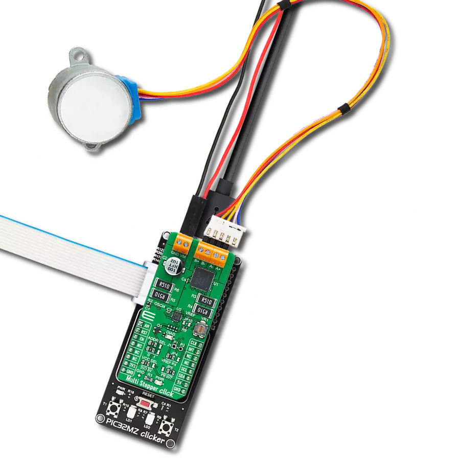
The 28BYJ-48 is an adaptable 5VDC stepper motor with a compact design, ideal for various applications. It features four phases, a speed variation ratio of 1/64, and a stride angle of 5.625°/64 steps, allowing precise control. The motor operates at a frequency of 100Hz and has a DC resistance of 50Ω ±7% at 25°C. It boasts an idle in-traction frequency greater than 600Hz and an idle out-traction frequency exceeding 1000Hz, ensuring reliability in different scenarios. With a self-positioning torque and in-traction torque both exceeding 34.3mN.m at 120Hz, the 28BYJ-48 offers robust performance. Its friction torque ranges from 600 to 1200 gf.cm, while the pull-in torque is 300 gf.cm. This motor makes a reliable and efficient choice for your stepper motor needs.

Used MCU Pins
mikroBUS™ mapper
Take a closer look
Click board™ Schematic

Step by step
Project assembly

Start by selecting your development board and Click board™. Begin with the Flip&Click PIC32MZ as your development board.


Track your results in real time
Application Output
1. Application Output - In Debug mode, the 'Application Output' window enables real-time data monitoring, offering direct insight into execution results. Ensure proper data display by configuring the environment correctly using the provided tutorial.

2. UART Terminal - Use the UART Terminal to monitor data transmission via a USB to UART converter, allowing direct communication between the Click board™ and your development system. Configure the baud rate and other serial settings according to your project's requirements to ensure proper functionality. For step-by-step setup instructions, refer to the provided tutorial.

3. Plot Output - The Plot feature offers a powerful way to visualize real-time sensor data, enabling trend analysis, debugging, and comparison of multiple data points. To set it up correctly, follow the provided tutorial, which includes a step-by-step example of using the Plot feature to display Click board™ readings. To use the Plot feature in your code, use the function: plot(*insert_graph_name*, variable_name);. This is a general format, and it is up to the user to replace 'insert_graph_name' with the actual graph name and 'variable_name' with the parameter to be displayed.

Software Support
Library Description
This library contains API for Stepper 16 Click driver.
Key functions:
stepper16_hard_reset- Resets device.stepper16_set_step_resolution- Set step resolution.stepper16_move_motor_angle- Move motor in angle value.
Open Source
Code example
The complete application code and a ready-to-use project are available through the NECTO Studio Package Manager for direct installation in the NECTO Studio. The application code can also be found on the MIKROE GitHub account.
/*!
 * @file main.c
 * @brief Stepper16 Click example
 *
 * # Description
 * This example showcases the device's ability to control the motor.
 * It initializes the device for control and moves the motor in two
 * directions in a variety of speeds and step resolutions for 360 degrees.
 *
 * The demo application is composed of two sections :
 *
 * ## Application Init
 * Initializes UART and SPI communication modules, and additional
 * pins for motor control, resets device, set's default configuration,
 * and reads its ID and sets
 *
 * ## Application Task
 * First it move motor clockwise for 360 degrees in medium speed and
 * full step resolution. Then changes direction and moves motor for
 * 180 degrees in slow speed and quarter step, and additional 180 degrees
 * in fast speed and 1/16 step resolution.
 *
 * @note
 * Device is powered by externam VM so for communication to work Click
 * board should be connected on power supply from 6V to 29V. At the start of
 * application user should reset device and read it's Status register 1 to clear it.
 * After that it can communicate with device and control it noramaly.
 *
 * @author Luka Filipovic
 *
 */

#include "board.h"
#include "log.h"
#include "stepper16.h"

static stepper16_t stepper16;
static log_t logger;

/**
 * @brief Check error
 * @details Checks if one of error flags in context
 * object is set and logs flag error.
 * @param[in] ctx : Click context object.
 * See #stepper18_t object definition for detailed explanation.
 * @return Nothing.
 */
static void check_error ( stepper16_t *ctx );

void application_init ( void )
{
    uint16_t read_data = 0;
    log_cfg_t log_cfg;  /**< Logger config object. */
    stepper16_cfg_t stepper16_cfg;  /**< Click config object. */

    /**
     * Logger initialization.
     * Default baud rate: 115200
     * Default log level: LOG_LEVEL_DEBUG
     * @note If USB_UART_RX and USB_UART_TX
     * are defined as HAL_PIN_NC, you will
     * need to define them manually for log to work.
     * See @b LOG_MAP_USB_UART macro definition for detailed explanation.
     */
    LOG_MAP_USB_UART( log_cfg );
    log_init( &logger, &log_cfg );
    log_info( &logger, " Application Init " );

    // Click initialization.
    stepper16_cfg_setup( &stepper16_cfg );
    STEPPER16_MAP_MIKROBUS( stepper16_cfg, MIKROBUS_1 );
    err_t init_flag  = stepper16_init( &stepper16, &stepper16_cfg );
    if ( init_flag == SPI_MASTER_ERROR )
    {
        log_error( &logger, " Application Init Error. " );
        log_info( &logger, " Please, run program again... " );

        for ( ; ; );
    }

    if ( STEPPER16_ERROR == stepper16_default_cfg ( &stepper16 ) )
    {
        log_error( &logger, " Default configuration. " );
        log_info( &logger, " Please, run program again... " );

        for ( ; ; );
    }

    stepper16_generic_read( &stepper16, STEPPER16_REG_SR4, &read_data );
    log_info( &logger, "DEV ID: %d ", ( read_data >> 3 ) );
    log_info( &logger, "REV ID: %d ", ( read_data & 3 ) );

    log_info( &logger, " Application Task " );
    stepper16_set_dir( &stepper16, 0 );
}

void application_task ( void )
{
    static uint8_t direction = 0;
    log_printf( &logger, "> Move 360deg in CW direction.\r\n" );
    stepper16_set_step_resolution( &stepper16, STEPPER16_STEP_RES_FULL );
    check_error( &stepper16 );
    stepper16_move_motor_angle( &stepper16, 360, STEPPER16_SPEED_MEDIUM );
    direction = !direction;
    stepper16_set_dir( &stepper16, direction );
    Delay_ms ( 500 );
    log_printf( &logger, "> Move 180deg in CCW direction.\r\n" );
    stepper16_set_step_resolution( &stepper16, STEPPER16_STEP_RES_QUARTER );
    check_error( &stepper16 );
    stepper16_move_motor_angle( &stepper16, 180, STEPPER16_SPEED_SLOW );
    Delay_ms ( 1000 );
    log_printf( &logger, "> Move 180deg in CCW direcion.\r\n" );
    stepper16_set_step_resolution( &stepper16, STEPPER16_STEP_RES_1div16 );
    check_error( &stepper16 );
    stepper16_move_motor_angle( &stepper16, 180, STEPPER16_SPEED_FAST );
    direction = !direction;
    stepper16_set_dir( &stepper16, direction );
    Delay_ms ( 1000 );
    Delay_ms ( 1000 );
}

int main ( void )
{
    /* Do not remove this line or clock might not be set correctly. */
    #ifdef PREINIT_SUPPORTED
    preinit();
    #endif

    application_init( );

    for ( ; ; )
    {
        application_task( );
    }

    return 0;
}

static void check_error ( stepper16_t *ctx )
{
    if ( ctx->spierr )
        log_error( &logger, "SPI" );
    if ( ctx->uv )
        log_error( &logger, "Under voltage detection." );
    if ( ctx->eldef )
        log_error( &logger, "Eletrical defect." );
    if ( ctx->tsd )
        log_error( &logger, "Thermal shutdown." );
    if ( ctx->tw )
        log_error( &logger, "Thermal warning." );
}

// ------------------------------------------------------------------------ END