Transform time into digital insights with TDC7200 and PIC32MZ2048EFH100
Counting moments, capturing dreams
Published May 27, 2023
Click board™
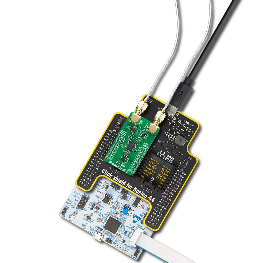
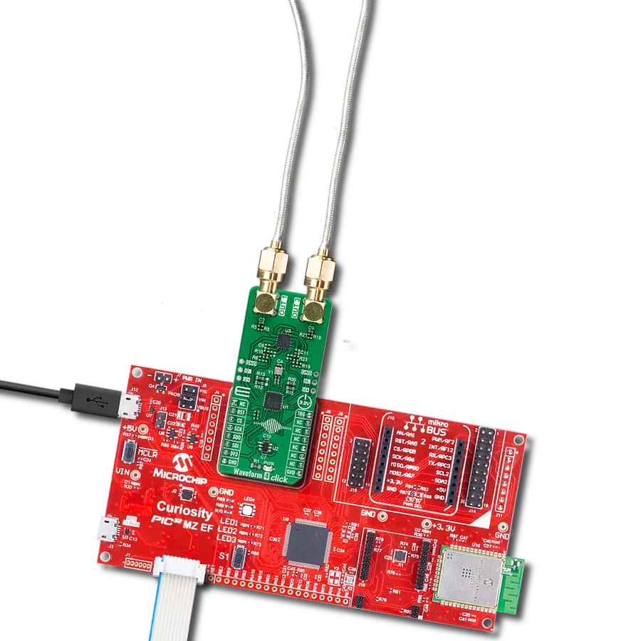
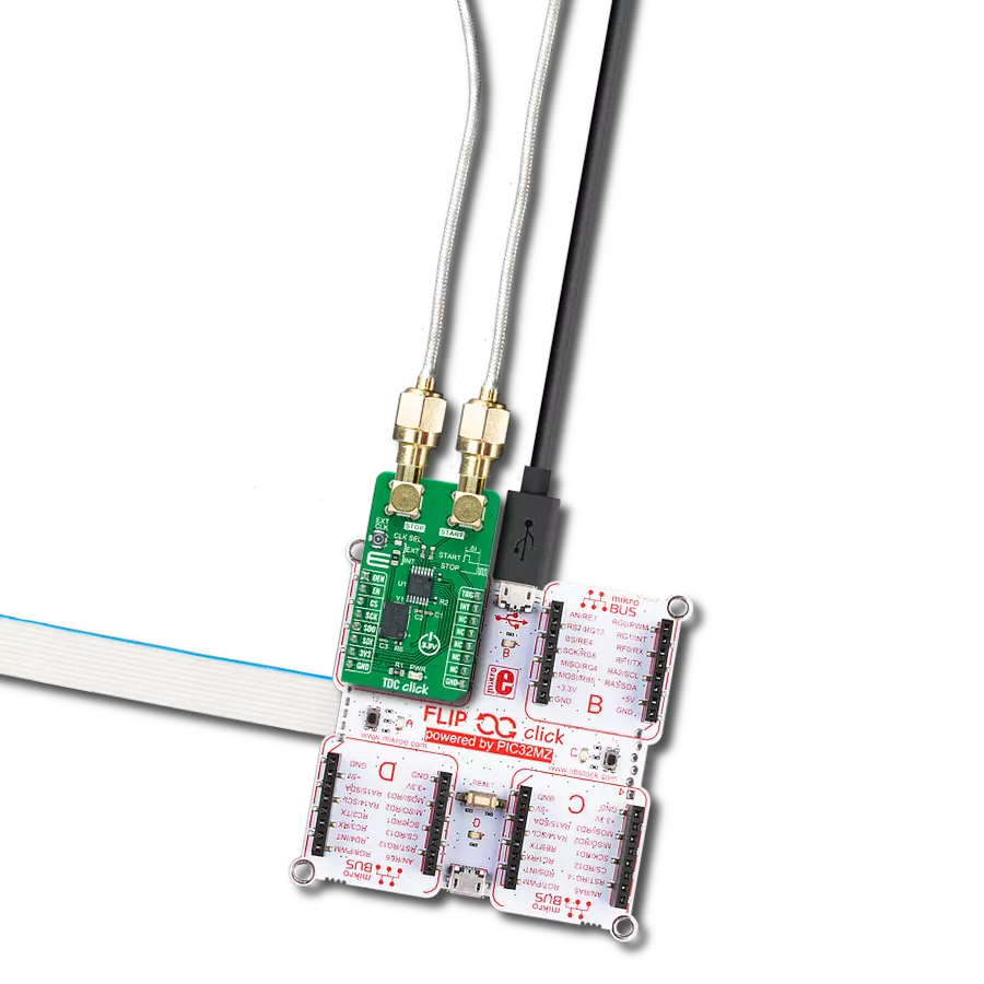
TDC Click
Dev. board
Flip&Click PIC32MZ
Compiler
NECTO Studio
MCU
PIC32MZ2048EFH100
Achieve unparalleled accuracy in time-of-flight and flow meter applications, particularly in zero and low flow measurements
A
A
Hardware Overview
How does it work?
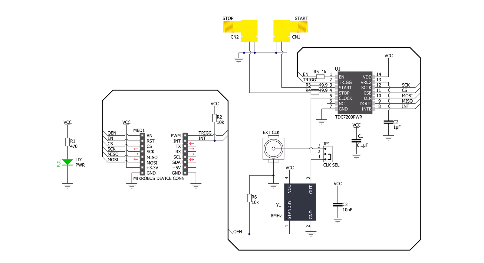
TDC Click is based on the TDC7200, a time-to-digital converter for time-of-flight (ToF) applications for LIDAR and ultrasonic from Texas Instruments. This stopwatch IC measures the time between a single event known as time-of-flight (an edge on START signal) and multiple subsequent events (an edge on STOP signal), which are brought to the onboard SMA connectors marked as START and STOP. The user also can pair this Click board™ with some external board that contains the TDC1000 (ultrasonic analog front-end) and become a part of a complete ultrasonic sensing solution for measurements such as water, gas, and heat flow meter. The TDC7200 has an internal self-calibrated time base compensating for drift over time and temperature used to measure time accurately in the order of picoseconds. When placed in the Autonomous Multi-Cycle
Averaging mode of operation, the TDC7200 can be optimized for low system power consumption. The host can sleep to save power, and the TDC can wake it up upon completion of the measurement sequence. The TDC7200 also has an external reference clock to calibrate the internal time base accurately. All digital circuits inside the device also use this reference clock; thus, the clock must be available and stable when the device is enabled. For this reason, there is the possibility of selecting an external clock connected to a miniature coaxial N.FL series connector or an internal one by an onboard 8MHz crystal that can be activated via an OEN pin routed on the AN pin of the mikroBUS™ socket. Selection can be performed by onboard SMD jumper labeled as CLK SEL to an appropriate position marked as EXT and INT.
The TDC7200 communicates with MCU using the standard SPI serial interface with a maximum frequency of 20MHz. In addition, it also uses several additional GPIO pins, such as the EN pin routed on the RST pin of the mikroBUS™ socket used as a reset to all digital circuits in the TDC7200, the TRG pin routed on the PWM pin of the mikroBUS™ socket as a start measurement trigger and INT pin which determine TDC measurement completion. This Click board™ can only be operated with a 3.3V logic voltage level. The board must perform appropriate logic voltage level conversion before using MCUs with different logic levels. However, the Click board™ comes equipped with a library containing functions and an example code that can be used as a reference for further development.

Features overview
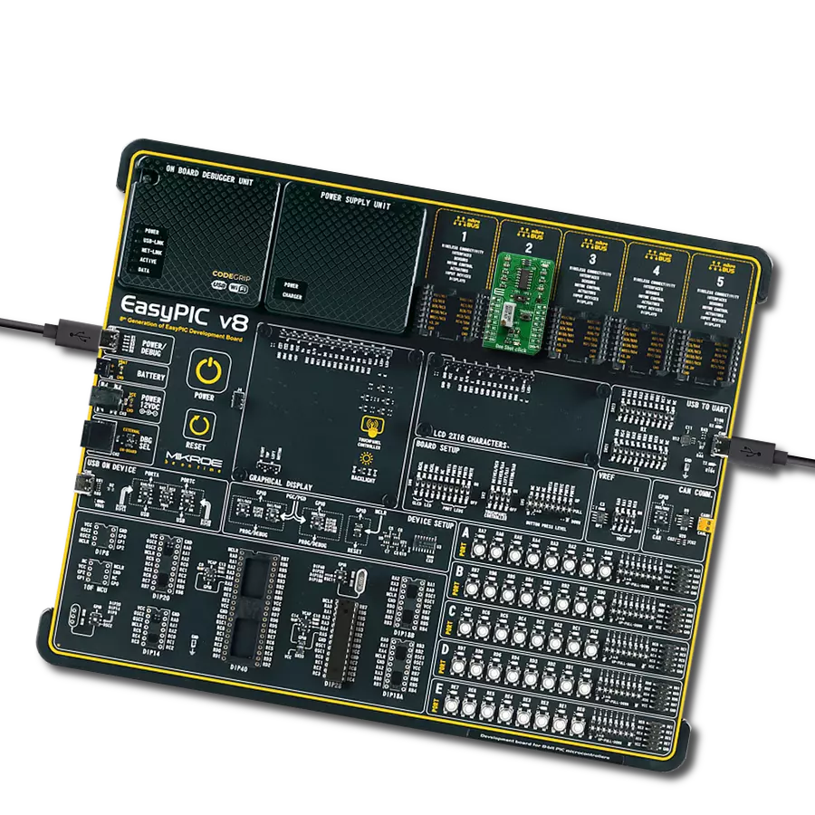
Development board
Flip&Click PIC32MZ is a compact development board designed as a complete solution that brings the flexibility of add-on Click boards™ to your favorite microcontroller, making it a perfect starter kit for implementing your ideas. It comes with an onboard 32-bit PIC32MZ microcontroller, the PIC32MZ2048EFH100 from Microchip, four mikroBUS™ sockets for Click board™ connectivity, two USB connectors, LED indicators, buttons, debugger/programmer connectors, and two headers compatible with Arduino-UNO pinout. Thanks to innovative manufacturing technology,
it allows you to build gadgets with unique functionalities and features quickly. Each part of the Flip&Click PIC32MZ development kit contains the components necessary for the most efficient operation of the same board. In addition, there is the possibility of choosing the Flip&Click PIC32MZ programming method, using the chipKIT bootloader (Arduino-style development environment) or our USB HID bootloader using mikroC, mikroBasic, and mikroPascal for PIC32. This kit includes a clean and regulated power supply block through the USB Type-C (USB-C) connector. All communication
methods that mikroBUS™ itself supports are on this board, including the well-established mikroBUS™ socket, user-configurable buttons, and LED indicators. Flip&Click PIC32MZ development kit allows you to create a new application in minutes. Natively supported by Mikroe software tools, it covers many aspects of prototyping thanks to a considerable number of different Click boards™ (over a thousand boards), the number of which is growing every day.

Microcontroller Overview
MCU Card / MCU

Architecture
PIC32
MCU Memory (KB)
2048
Silicon Vendor
Microchip
Pin count
100
RAM (Bytes)
524288
Used MCU Pins
mikroBUS™ mapper
Take a closer look
Click board™ Schematic
Step by step
Project assembly

Start by selecting your development board and Click board™. Begin with the Flip&Click PIC32MZ as your development board.


Track your results in real time
Application Output
1. Application Output - In Debug mode, the 'Application Output' window enables real-time data monitoring, offering direct insight into execution results. Ensure proper data display by configuring the environment correctly using the provided tutorial.

2. UART Terminal - Use the UART Terminal to monitor data transmission via a USB to UART converter, allowing direct communication between the Click board™ and your development system. Configure the baud rate and other serial settings according to your project's requirements to ensure proper functionality. For step-by-step setup instructions, refer to the provided tutorial.

3. Plot Output - The Plot feature offers a powerful way to visualize real-time sensor data, enabling trend analysis, debugging, and comparison of multiple data points. To set it up correctly, follow the provided tutorial, which includes a step-by-step example of using the Plot feature to display Click board™ readings. To use the Plot feature in your code, use the function: plot(*insert_graph_name*, variable_name);. This is a general format, and it is up to the user to replace 'insert_graph_name' with the actual graph name and 'variable_name' with the parameter to be displayed.

Software Support
Library Description
This library contains API for TDC Click driver.
Key functions:
tdc_cfg_setup- Config Object Initialization function.tdc_init- Initialization function.tdc_default_cfg- Click Default Configuration function.
Open Source
Code example
The complete application code and a ready-to-use project are available through the NECTO Studio Package Manager for direct installation in the NECTO Studio. The application code can also be found on the MIKROE GitHub account.
/*!
 * @file main.c
 * @brief Tdc Click example
 *
 * # Description
 * This library contains an API for the TDC Click driver.
 * This demo application shows the use of a TDC Click board™.
 *
 * The demo application is composed of two sections :
 *
 * ## Application Init
 * Initialization of SPI module and log UART.
 * After driver initialization, the app set default settings and
 * the configures the measurement ( set the pulse to 100 us ).
 *
 * ## Application Task
 * This is an example that shows the use of a TDC Click board™.
 * In this example, after the START signal, the app sends 3 STOP signals per 100 microseconds.
 * The application reads and displays the value of Time, Clock count and
 * Time-of-Flight values of three performed measurements.
 * Results are being sent to the Usart Terminal where you can track their changes.
 *
 * @author Nenad Filipovic
 *
 */

#include "board.h"
#include "log.h"
#include "tdc.h"

static tdc_t tdc;
static tdc_t tdc_pulse;
static log_t logger;
static uint16_t pulse_us;
static uint8_t count_stop;
static uint8_t num_stops;

void application_init ( void )
{
    log_cfg_t log_cfg;  /**< Logger config object. */
    tdc_cfg_t tdc_cfg;  /**< Click config object. */
    tdc_cfg_t tdc_cfg1;
    static uint8_t cal_periods;
    static uint8_t avg_cycles;
    static uint8_t sel_mode;

    /**
     * Logger initialization.
     * Default baud rate: 115200
     * Default log level: LOG_LEVEL_DEBUG
     * @note If USB_UART_RX and USB_UART_TX
     * are defined as HAL_PIN_NC, you will
     * need to define them manually for log to work.
     * See @b LOG_MAP_USB_UART macro definition for detailed explanation.
     */
    LOG_MAP_USB_UART( log_cfg );
    log_init( &logger, &log_cfg );
    log_info( &logger, " Application Init " );

    // Click initialization.

    tdc_cfg_setup( &tdc_cfg );
    TDC_MAP_MIKROBUS( tdc_cfg, MIKROBUS_1 );
    tdc_cfg_setup( &tdc_cfg1 );
    TDC_MAP_MIKROBUS( tdc_cfg1, MIKROBUS_2 );
    err_t init_flag  = tdc_init( &tdc, &tdc_cfg );
    init_flag  |= tdc_init( &tdc_pulse,  &tdc_cfg1 );
    if ( SPI_MASTER_ERROR == init_flag )
    {
        log_error( &logger, " Application Init Error. " );
        log_info( &logger, " Please, run program again... " );

        for ( ; ; );
    }

    tdc_default_cfg ( &tdc );
    log_info( &logger, " Application Task " );
    Delay_ms ( 100 );

    cal_periods = 10;
    avg_cycles = 1;
    num_stops = 3;
    sel_mode = 1;
    pulse_us = 100;
    count_stop = 1;
    tdc_setup_measurement( &tdc, cal_periods, avg_cycles, num_stops, sel_mode );
    log_printf( &logger, "---------------------------\r\n" );
    Delay_ms ( 100 );
}

void application_task ( void )
{
    static uint32_t p_time[ 5 ];
    static uint32_t p_clock_count[ 5 ];
    static uint32_t p_tof[ 5 ];

    tdc_start_measurement( &tdc );

    while ( tdc_get_trg( &tdc ) == 0 );

    tdc_gen_pulse( &tdc_pulse, pulse_us, num_stops );

    while ( tdc_get_interrupt( &tdc ) == 1 );

    tdc_get_measurement( &tdc, TDC_MCU_CLOCK_MODE_168_MHZ, count_stop, p_time, p_clock_count, p_tof );

    log_printf( &logger, " Time[ 0 ]        = %lu\r\n", p_time[ 0 ] );
    log_printf( &logger, " Time[ 1 ]        = %lu\r\n", p_time[ 1 ] );
    log_printf( &logger, " Time[ 2 ]        = %lu\r\n", p_time[ 2 ] );
    log_printf( &logger, "- - - - - - - - - - - - - -\r\n" );

    log_printf( &logger, " Clock count[ 0 ] = %lu\r\n", p_clock_count[ 0 ] );
    log_printf( &logger, " Clock count[ 1 ] = %lu\r\n", p_clock_count[ 1 ] );
    log_printf( &logger, " Clock count[ 2 ] = %lu\r\n", p_clock_count[ 2 ] );
    log_printf( &logger, "- - - - - - - - - - - - - -\r\n" );

    log_printf( &logger, " TOF[ 0 ]         = %u us\r\n", p_tof[ 0 ] );
    log_printf( &logger, " TOF[ 1 ]         = %u us\r\n", p_tof[ 1 ] );
    log_printf( &logger, " TOF[ 2 ]         = %u us\r\n", p_tof[ 2 ] );
    log_printf( &logger, "---------------------------\r\n" );
    Delay_ms ( 1000 );
}

int main ( void )
{
    /* Do not remove this line or clock might not be set correctly. */
    #ifdef PREINIT_SUPPORTED
    preinit();
    #endif

    application_init( );

    for ( ; ; )
    {
        application_task( );
    }

    return 0;
}

// ------------------------------------------------------------------------ END