Maximize your energy with TPS61230A and PIC32MZ2048EFH100
Power up your possibilities
Published Jul 27, 2023
Click board™
Boost 4 click
Dev. board
Flip&Click PIC32MZ
Compiler
NECTO Studio
MCU
PIC32MZ2048EFH100
Add a voltage boost solution to your engineering project and take your power management to the next level
A
A
Hardware Overview
How does it work?
Boost 4 Click is based on the TPS61230A, a high-efficiency, fully integrated synchronous boost converter from Texas Instruments. The Click is designed to run on a 3.3V power supply. Boost 4 Click drives the target chip through the digital potentiometer, which has SPI communication with the microcontroller on the system. Boost 4 Click is the power management solution for your next project. Boost 4 Click provides an adjustable output voltage through the SPI DAC that drives
the FB pin to set desired voltage. The Click can deliver up to 2.4-A output current at a 5V output with the 2.5-V input supply. The TPS61230A also integrates 6-A, 21-mΩ, and 18-mΩ power switches. During the light load condition, the TPS61230A automatically enters into the PFM operation to maximize the efficiency with the lowest quiescent current. In the shutdown by pulling EN pin to the logic low, the load is completely disconnected from the input, and the input current
consumption is reduced to below 1.0μA. This Click board™ can be operated only with a 3.3V logic voltage level. The board must perform appropriate logic voltage level conversion before using MCUs with different logic levels. Also, it comes equipped with a library containing functions and an example code that can be used, as a reference, for further development.

Features overview
Development board
Flip&Click PIC32MZ is a compact development board designed as a complete solution that brings the flexibility of add-on Click boards™ to your favorite microcontroller, making it a perfect starter kit for implementing your ideas. It comes with an onboard 32-bit PIC32MZ microcontroller, the PIC32MZ2048EFH100 from Microchip, four mikroBUS™ sockets for Click board™ connectivity, two USB connectors, LED indicators, buttons, debugger/programmer connectors, and two headers compatible with Arduino-UNO pinout. Thanks to innovative manufacturing technology,
it allows you to build gadgets with unique functionalities and features quickly. Each part of the Flip&Click PIC32MZ development kit contains the components necessary for the most efficient operation of the same board. In addition, there is the possibility of choosing the Flip&Click PIC32MZ programming method, using the chipKIT bootloader (Arduino-style development environment) or our USB HID bootloader using mikroC, mikroBasic, and mikroPascal for PIC32. This kit includes a clean and regulated power supply block through the USB Type-C (USB-C) connector. All communication
methods that mikroBUS™ itself supports are on this board, including the well-established mikroBUS™ socket, user-configurable buttons, and LED indicators. Flip&Click PIC32MZ development kit allows you to create a new application in minutes. Natively supported by Mikroe software tools, it covers many aspects of prototyping thanks to a considerable number of different Click boards™ (over a thousand boards), the number of which is growing every day.

Microcontroller Overview
MCU Card / MCU

Architecture
PIC32
MCU Memory (KB)
2048
Silicon Vendor
Microchip
Pin count
100
RAM (Bytes)
524288
Used MCU Pins
mikroBUS™ mapper
Take a closer look
Click board™ Schematic

Step by step
Project assembly

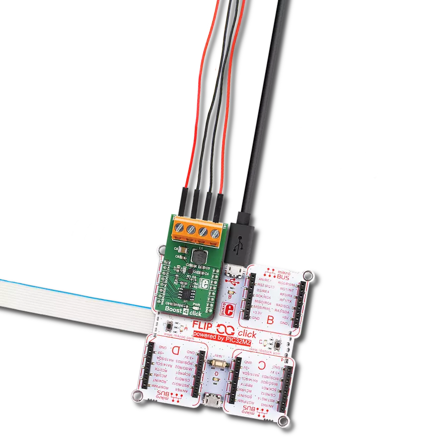
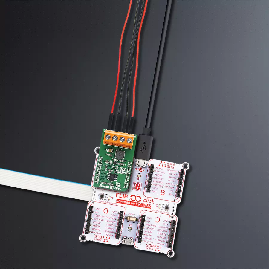
Start by selecting your development board and Click board™. Begin with the Flip&Click PIC32MZ as your development board.


Software Support
Library Description
This library contains API for Boost 4 Click driver.
Key functions:
boost4_generic_transfer- Generic SPI transfer, for sending and receiving packagesboost4_set_out_voltage- Function set output voltage by write 12-bit data to the register on the TPS61230A High Efficiency Step-Up Converter of Boost 4 Clickboost4_enable- Function is used to enabled or disabled the device
Open Source
Code example
The complete application code and a ready-to-use project are available through the NECTO Studio Package Manager for direct installation in the NECTO Studio. The application code can also be found on the MIKROE GitHub account.
/*!
 * \file
 * \brief Boost4 Click example
 *
 * # Description
 * This example demonstrates the use of Boost 4 Click board.
 *
 * The demo application is composed of two sections :
 *
 * ## Application Init
 * Initializes the driver and logger, and enables the Click board.
 *
 * ## Application Task
 * Set the desired output voltage by cycling through a couple of predefined voltage values.
 * All data are being logged on USB UART every 3 seconds.
 *
 * @note
 * Vout cannot be set to voltage below Vin. So in order to get all values at Vout exactly
 * as it is set in this example, please provide 2.5V to Vin.
 *
 * \author Jovan Stajkovic
 *
 */
// ------------------------------------------------------------------- INCLUDES

#include "board.h"
#include "log.h"
#include "boost4.h"

// ------------------------------------------------------------------ VARIABLES

static boost4_t boost4;
static log_t logger;

// ------------------------------------------------------ APPLICATION FUNCTIONS

void application_init ( void )
{
    log_cfg_t log_cfg;
    boost4_cfg_t cfg;

    /**
     * Logger initialization.
     * Default baud rate: 115200
     * Default log level: LOG_LEVEL_DEBUG
     * @note If USB_UART_RX and USB_UART_TX
     * are defined as HAL_PIN_NC, you will
     * need to define them manually for log to work.
     * See @b LOG_MAP_USB_UART macro definition for detailed explanation.
     */
    LOG_MAP_USB_UART( log_cfg );
    log_init( &logger, &log_cfg );
    log_info( &logger, "---- Application Init ----" );

    //  Click initialization.

    boost4_cfg_setup( &cfg );
    BOOST4_MAP_MIKROBUS( cfg, MIKROBUS_1 );
    boost4_init( &boost4, &cfg );
    log_printf( &logger, "-----------------------------\r\n" );
    log_printf( &logger, "        Boost 4 Click        \r\n" );
    log_printf( &logger, "-----------------------------\r\n" );
    boost4_enable( &boost4, BOOST4_ENABLE );
    Delay_ms ( 1000 );
}

void application_task ( void )
{
    log_printf( &logger, " Set the max Vout \r\n" );
    boost4_set_out_voltage( &boost4, BOOST4_VOUT_MAX );

    Delay_ms ( 1000 );
    Delay_ms ( 1000 );
    Delay_ms ( 1000 );

    log_printf( &logger, "-----------------------------\r\n" );

    log_printf( &logger, " Set Vout to 5V\r\n" );

    boost4_set_out_voltage( &boost4, BOOST4_VOUT_5 );

    Delay_ms ( 1000 );
    Delay_ms ( 1000 );
    Delay_ms ( 1000 );

    log_printf( &logger, "-----------------------------\r\n" );

    log_printf( &logger, " Set Vout to 4.5V\r\n" );

    boost4_set_out_voltage( &boost4, BOOST4_VOUT_4_5 );

    Delay_ms ( 1000 );
    Delay_ms ( 1000 );
    Delay_ms ( 1000 );

    log_printf( &logger, "-----------------------------\r\n" );

    log_printf( &logger, " Set Vout to 4V\r\n" );

    boost4_set_out_voltage( &boost4, BOOST4_VOUT_4 );

    Delay_ms ( 1000 );
    Delay_ms ( 1000 );
    Delay_ms ( 1000 );

    log_printf( &logger, "-----------------------------\r\n" );

    log_printf( &logger, " Set Vout to 3.5V\r\n" );

    boost4_set_out_voltage( &boost4, BOOST4_VOUT_3_5 );

    Delay_ms ( 1000 );
    Delay_ms ( 1000 );
    Delay_ms ( 1000 );

    log_printf( &logger, "-----------------------------\r\n" );

    log_printf( &logger, " Set Vout to 3V\r\n" );

    boost4_set_out_voltage( &boost4, BOOST4_VOUT_3 );

    Delay_ms ( 1000 );
    Delay_ms ( 1000 );
    Delay_ms ( 1000 );

    log_printf( &logger, "-----------------------------\r\n" );

    log_printf( &logger, " Set Vout to 2.5V\r\n" );

    boost4_set_out_voltage( &boost4, BOOST4_VOUT_2_5 );

    Delay_ms ( 1000 );
    Delay_ms ( 1000 );
    Delay_ms ( 1000 );

    log_printf( &logger, "-----------------------------\r\n" );

    log_printf( &logger, " Set the min Vout \r\n" );

    boost4_set_out_voltage( &boost4, BOOST4_VOUT_MIN );

    Delay_ms ( 1000 );
    Delay_ms ( 1000 );
    Delay_ms ( 1000 );

    log_printf( &logger, "-----------------------------\r\n" );
}

int main ( void )
{
    /* Do not remove this line or clock might not be set correctly. */
    #ifdef PREINIT_SUPPORTED
    preinit();
    #endif

    application_init( );

    for ( ; ; )
    {
        application_task( );
    }

    return 0;
}


// ------------------------------------------------------------------------ END
Additional Support
Resources
Category:Boost


