Illuminate, animate, and inspire with WS2812 and PIC32MZ2048EFH100
Pixels awaken!

Published Sep 05, 2023
Click board™
10x10 RGB Click
Dev Board
Flip&Click PIC32MZ
Compiler
NECTO Studio
MCU
PIC32MZ2048EFH100
Our solution, featuring a 10x10 display matrix of 100 'intelligent' RGB elements, transforms your creative ideas into mesmerizing visuals, making it the ultimate choice for dynamic displays, animations, and interactive presentations
A
A
Hardware Overview
How does it work?
10x10 RGB Click is based on the WS2812, an intelligent control LED light source from Worldsemi. Its exterior adopts the latest MOLDING packaging technology, and the control circuit and RGB chips are integrated into a package of 2020 components. It's internal includes an intelligent digital port data latch and signal reshaping amplification drive circuit. It also includes a precision internal oscillator and a voltage-programmable constant current control part, ensuring consistent pixel point light color height. The data transfer protocol use single NZR communication mode. After the pixel power-on reset, the DIN port receive data from controller, the first pixel collect initial 24bit data then sent to the internal data latch, the other data which reshaping by the internal signal reshaping amplification circuit sent to the next cascade pixel through the DO port. After transmission for each
pixel, the signal to reduce 24bit. pixel adopt auto reshaping transmit technology, making the pixel cascade number is not limited the signal transmission, only depend on the speed of signal transmission. RESET time >280μs , it won't cause wrong reset while interruption, it supports the lower frequency and inexpensive MCU. Refresh Frequency updates to 2KHz, Low Frame Frequency and No Flicker appear in HD Video Camera, it improve excellent display effect. LED with low driving voltage, environmental protection and energy saving, high brightness, large scattering angle, good consistency, low power, long life and other advantages. The control chip integrated in LED above becoming more simple circuit, small volume, convenient installation. 10x10 RGB Click can be used in many applications, like full-color module, full color soft lights a lamp strip, LED decorative lighting, indoor/outdoor LED
irregular screen, game machine and amusement equipment, and more. The INT pin of the mikroBUS™, which is labeled as DO on this Click board™, allows cascading of multiple 10x10 RGB click devices. It simply routes the data line back to the mikroBUS™, allowing it to be re-used for the next 10x10 RGB click, and so on. The length of the whole chain is limited only by the communication speed, required to scan through all the LED devices, in order to maintain a reasonable refresh speed. This Click board™ can be operated only with a 3.3V logic voltage level. The board must perform appropriate logic voltage level conversion before using MCUs with different logic levels. Also, it comes equipped with a library containing functions and an example code that can be used as a reference for further development.


Features overview
Development board
Flip&Click PIC32MZ is a compact development board designed as a complete solution that brings the flexibility of add-on Click boards™ to your favorite microcontroller, making it a perfect starter kit for implementing your ideas. It comes with an onboard 32-bit PIC32MZ microcontroller, the PIC32MZ2048EFH100 from Microchip, four mikroBUS™ sockets for Click board™ connectivity, two USB connectors, LED indicators, buttons, debugger/programmer connectors, and two headers compatible with Arduino-UNO pinout. Thanks to innovative manufacturing technology,
it allows you to build gadgets with unique functionalities and features quickly. Each part of the Flip&Click PIC32MZ development kit contains the components necessary for the most efficient operation of the same board. In addition, there is the possibility of choosing the Flip&Click PIC32MZ programming method, using the chipKIT bootloader (Arduino-style development environment) or our USB HID bootloader using mikroC, mikroBasic, and mikroPascal for PIC32. This kit includes a clean and regulated power supply block through the USB Type-C (USB-C) connector. All communication
methods that mikroBUS™ itself supports are on this board, including the well-established mikroBUS™ socket, user-configurable buttons, and LED indicators. Flip&Click PIC32MZ development kit allows you to create a new application in minutes. Natively supported by Mikroe software tools, it covers many aspects of prototyping thanks to a considerable number of different Click boards™ (over a thousand boards), the number of which is growing every day.

Microcontroller Overview
MCU Card / MCU

Architecture
PIC32
MCU Memory (KB)
2048
Silicon Vendor
Microchip
Pin count
100
RAM (Bytes)
524288
Used MCU Pins
mikroBUS™ mapper
Take a closer look
Schematic

Step by step
Project assembly

Start by selecting your development board and Click board™. Begin with the Flip&Click PIC32MZ as your development board.


Track your results in real time
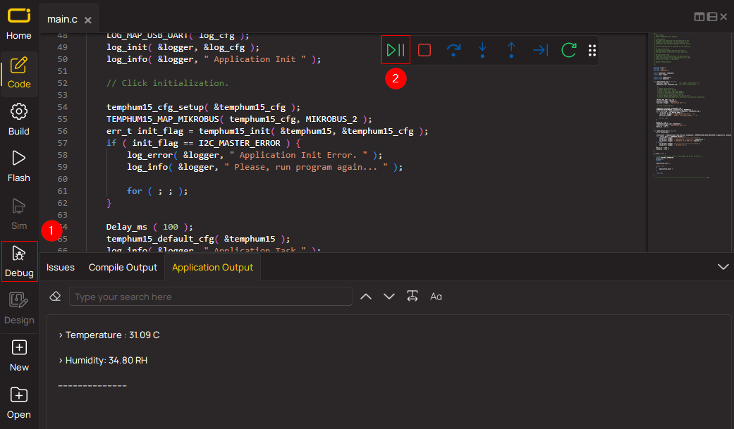
Application Output via Debug Mode
1. Once the code example is loaded, pressing the "DEBUG" button initiates the build process, programs it on the created setup, and enters Debug mode.
2. After the programming is completed, a header with buttons for various actions within the IDE becomes visible. Clicking the green "PLAY" button starts reading the results achieved with the Click board™. The achieved results are displayed in the Application Output tab.
Software Support
Library Description
This library contains API for 10x10 RGB Click driver.
Key functions:
c10x10rgb_display_image- This function displays an image from the specified demo_image addressc10x10rgb_display_byte- This function displays the specified bytec10x10rgb_display_string- This function displays the specified string.
Open Source
Code example
This example can be found in NECTO Studio. Feel free to download the code, or you can copy the code below.
/*!
 * \file
 * \brief 10x10 RGB Click example
 *
 * # Description
 * This example showcases how to initialize, configure and use the 10x10 RGB click moduel. The
 * click has a 10 by 10 RGB LED matrix which can be programmed to show different colors or even
 * images. LED elements that form the matrix communicate by a single line with the host MCU.
 *
 * The demo application is composed of two sections :
 *
 * ## Application Init
 * This function initializes and configures the click board.
 *
 * ## Application Task
 * This function first displays 3 chars { R, G, B }, the string "MIKROE", the company logo and
 * a rainbow in the end.
 *
 * @note
 * Timing sequence chart:
 *          -----------|     T0L
 *              T0H    |______________
 * Logic 0:
 *          T0H ~ 200-400ns
 *          T0L ~ 600-1000ns
 *
 *          -----------|     T1L
 *              T1H    |______________
 * Logic 1:
 *          T1H ~ 600-1000ns
 *          T1L ~ 600-1000ns
 *
 * \author MikroE Team
 *
 */
// ------------------------------------------------------------------- INCLUDES

#include "board.h"
#include "c10x10rgb.h"

// Delay adjustment for specific systems.
#ifdef __MIKROC_AI__
    #ifdef STM32F407ZG
        /*< Adjusted for STM32F407ZG */
        #define DELAY_TOH Delay_Cyc( 3 );   // ~280ns
        #define DELAY_TOL Delay_Cyc( 7 );   // ~790ns
        #define DELAY_T1H Delay_Cyc( 12 );  // ~820ns
        #define DELAY_T1L Delay_Cyc( 8 );   // ~840ns
    #elif MK64FN1M0VDC12
        /*< Adjusted for MK64FN1M0VDC12 */
        #define DELAY_TOH \
                    asm nop; \
                    asm nop; \
                    asm nop; \
                    asm nop; \
                    asm nop; \
                    asm nop; \
                    asm nop; \
                    asm nop; \
                    asm nop; \
                    asm nop; \
                    asm nop; \
                    asm nop;                // ~280ns
        #define DELAY_TOL Delay_Cyc( 2 );   // ~880ns
        #define DELAY_T1H Delay_Cyc( 8 );   // ~800ns
        #define DELAY_T1L Delay_Cyc( 2 );   // ~800ns
    #elif TM4C129XNCZAD
        /*< Adjusted for TM4C129XNCZAD */
        #define DELAY_TOH                   // ~320ns
        #define DELAY_TOL asm nop;          // ~780ns
        #define DELAY_T1H Delay_Cyc( 6 );   // ~860ns
        #define DELAY_T1L                   // ~800ns
    #elif PIC32MX795F512L
        /*< Adjusted for PIC32MX795F512L */
        #define DELAY_TOH                   // ~300ns
        #define DELAY_TOL                   // ~940ns
        #define DELAY_T1H Delay_Cyc( 3 );   // ~780ns
        #define DELAY_T1L                   // ~940ns
    #else
        #error "Logic delays are not defined for the selected MCU"
    #endif
#elif __GNUC__
    #ifdef STM32F407ZG
        /*< Adjusted for STM32F407ZG */
        #define DELAY_TOH \
                    asm("nop"); \
                    asm("nop"); \
                    asm("nop"); \
                    asm("nop"); \
                    asm("nop"); \
                    asm("nop"); \
                    asm("nop"); \
                    asm("nop"); \
                    asm("nop"); \
                    asm("nop"); \
                    asm("nop"); \
                    asm("nop"); \
                    asm("nop"); \
                    asm("nop");             // ~300ns
        #define DELAY_TOL Delay_Cyc( 2 );   // ~840ns
        #define DELAY_T1H Delay_Cyc( 7 );   // ~810ns
        #define DELAY_T1L Delay_Cyc( 2 );   // ~830ns
    #elif MK64
        /*< Adjusted for MK64FN1M0VDC12 */
        #define DELAY_TOH \
                    asm("nop"); \
                    asm("nop"); \
                    asm("nop"); \
                    asm("nop"); \
                    asm("nop"); \
                    asm("nop");             // ~300ns
        #define DELAY_TOL  \
                    asm("nop"); \
                    asm("nop"); \
                    asm("nop"); \
                    asm("nop"); \
                    asm("nop"); \
                    asm("nop"); \
                    asm("nop"); \
                    asm("nop"); \
                    asm("nop"); \
                    asm("nop"); \
                    asm("nop"); \
                    asm("nop"); \
                    asm("nop"); \
                    asm("nop"); \
                    asm("nop"); \
                    asm("nop");             // ~720ns
        #define DELAY_T1H Delay_Cyc( 7 );   // ~780ns
        #define DELAY_T1L Delay_Cyc( 2 );   // ~900ns
    #elif TM4C129
        /*< Adjusted for TM4C129XNCZAD */
        #define DELAY_TOH                   // ~350ns
        #define DELAY_TOL                   // ~900ns
        #define DELAY_T1H Delay_Cyc( 2 );   // ~880ns
        #define DELAY_T1L                   // ~900ns
    #elif GD32VF103VBT6
        /*< Adjusted for GD32VF103VBT6 */
        #define DELAY_TOH \
                    asm("nop"); \
                    asm("nop"); \
                    asm("nop"); \
                    asm("nop");             // ~290ns
        #define DELAY_TOL \
                    asm("nop"); \
                    asm("nop"); \
                    asm("nop"); \
                    asm("nop"); \
                    asm("nop"); \
                    asm("nop"); \
                    asm("nop"); \
                    asm("nop");             // ~690ns
        #define DELAY_T1H Delay_Cyc( 2 );   // ~730ns
        #define DELAY_T1L \
                    asm("nop"); \
                    asm("nop"); \
                    asm("nop"); \
                    asm("nop"); \
                    asm("nop"); \
                    asm("nop"); \
                    asm("nop"); \
                    asm("nop"); \
                    asm("nop"); \
                    asm("nop"); \
                    asm("nop"); \
                    asm("nop");            // ~680ns
    #else
        #error "Logic delays are not defined for the selected MCU"
    #endif
#else
    #error "Logic delays are not defined for the selected toolchain"
#endif

// ------------------------------------------------------------------ VARIABLES

static c10x10rgb_t c10x10rgb;

const uint32_t MIKROE_IMAGE[ 100 ] =
{
    0x000000,0x000000,0x000000,0x000000,0x000000,0x000000,0x000000,0x000000,0x000000,0x000000,
    0x000000,0x000000,0x000000,0x000000,0x000000,0x000000,0x000000,0x000000,0x000000,0x000000,
    0x000000,0x000000,0x181800,0x181800,0x181800,0x181800,0x181800,0x181800,0x181800,0x000000,
    0x000000,0x181800,0x000000,0x000000,0x000000,0x000000,0x000000,0x000000,0x000000,0x000000,
    0x000000,0x181800,0x181800,0x181800,0x181800,0x181800,0x181800,0x181800,0x181800,0x000000,
    0x000000,0x181800,0x181800,0x181800,0x181800,0x181800,0x181800,0x181800,0x181800,0x000000,
    0x000000,0x181800,0x000000,0x000000,0x000000,0x000000,0x000000,0x000000,0x000000,0x000000,
    0x000000,0x000000,0x181800,0x181800,0x181800,0x181800,0x181800,0x181800,0x181800,0x000000,
    0x000000,0x000000,0x000000,0x000000,0x000000,0x000000,0x000000,0x000000,0x000000,0x000000,
    0x000000,0x000000,0x000000,0x000000,0x000000,0x000000,0x000000,0x000000,0x000000,0x000000
};

static c10x10rgb_byte_t scroll_data_obj[ 6 ] =
{
    { 'M', C10X10RGB_COLOR_OFF, C10X10RGB_COLOR_YELLOW_25, C10X10RGB_SCROLL_ROTATE_V },
    { 'I', C10X10RGB_COLOR_OFF, C10X10RGB_COLOR_YELLOW_25, C10X10RGB_SCROLL_ROTATE_V },
    { 'K', C10X10RGB_COLOR_OFF, C10X10RGB_COLOR_YELLOW_25, C10X10RGB_SCROLL_ROTATE_V },
    { 'R', C10X10RGB_COLOR_OFF, C10X10RGB_COLOR_YELLOW_25, C10X10RGB_SCROLL_ROTATE_V },
    { 'O', C10X10RGB_COLOR_OFF, C10X10RGB_COLOR_YELLOW_25, C10X10RGB_SCROLL_ROTATE_V },
    { 'E', C10X10RGB_COLOR_YELLOW_25, C10X10RGB_COLOR_OFF, C10X10RGB_SCROLL_ROTATE_V }
};

static uint16_t scroll_speed_ms = 100;
static uint8_t scroll_data_len = 6;

static c10x10rgb_byte_t rgb_data_byte[ 3 ] =
{
    { 'R', C10X10RGB_COLOR_RED_25, C10X10RGB_COLOR_OFF, C10X10RGB_BYTE_ROTATE_H_UP },
    { 'G', C10X10RGB_COLOR_OFF, C10X10RGB_COLOR_GREEN_25, C10X10RGB_BYTE_ROTATE_H_UP },
    { 'B', C10X10RGB_COLOR_BLUE_25, C10X10RGB_COLOR_OFF, C10X10RGB_BYTE_ROTATE_H_UP }
};

static uint8_t rainbow_brightness = 10;
static uint16_t rainbow_speed_ms = 20;

// ------------------------------------------------------- ADDITIONAL FUNCTIONS

static void logic_zero ( void )
{
    hal_ll_gpio_set_pin_output( &c10x10rgb.di_pin.pin );
    DELAY_TOH;
    hal_ll_gpio_clear_pin_output( &c10x10rgb.di_pin.pin );
    DELAY_TOL;
}

static void logic_one ( void )
{
    hal_ll_gpio_set_pin_output( &c10x10rgb.di_pin.pin );
    DELAY_T1H;
    hal_ll_gpio_clear_pin_output( &c10x10rgb.di_pin.pin );
    DELAY_T1L;
}

// ------------------------------------------------------ APPLICATION FUNCTIONS

void application_init ( void )
{
    c10x10rgb_cfg_t cfg;

    //  Click initialization.
    c10x10rgb_cfg_setup( &cfg, &logic_zero, &logic_one );
    C10X10RGB_MAP_MIKROBUS( cfg, MIKROBUS_1 );
    c10x10rgb_init( &c10x10rgb, &cfg );

    c10x10rgb_fill_screen( &c10x10rgb, C10X10RGB_COLOR_OFF );
    Delay_ms( 1000 );
}

void application_task ( void )
{
    c10x10rgb_display_byte ( &c10x10rgb, &rgb_data_byte[ 0 ] );
    Delay_ms( 1000 );
    c10x10rgb_display_byte ( &c10x10rgb, &rgb_data_byte[ 1 ] );
    Delay_ms( 1000 );
    c10x10rgb_display_byte ( &c10x10rgb, &rgb_data_byte[ 2 ] );
    Delay_ms( 2000 );

    c10x10rgb_display_string( &c10x10rgb, &scroll_data_obj, scroll_data_len, scroll_speed_ms );
    Delay_ms( 1000 );
    c10x10rgb_display_image( &c10x10rgb, &MIKROE_IMAGE[ 0 ] );
    Delay_ms( 3000 );
    c10x10rgb_demo_rainbow( &c10x10rgb, rainbow_brightness, rainbow_speed_ms );
    Delay_ms( 1000 );
}

int main ( void )
{
    application_init( );

    for ( ; ; )
    {
        application_task( );
    }

    return 0;
}

// ------------------------------------------------------------------------ END


